Calling all input circuit genius type people
 07-31-2008, 04:32 PM
#1
Junior Member
Thread Starter
iTrader: (1)

Join Date: Apr 2008
Location: Bristol
Posts: 439
Total Cats: 0
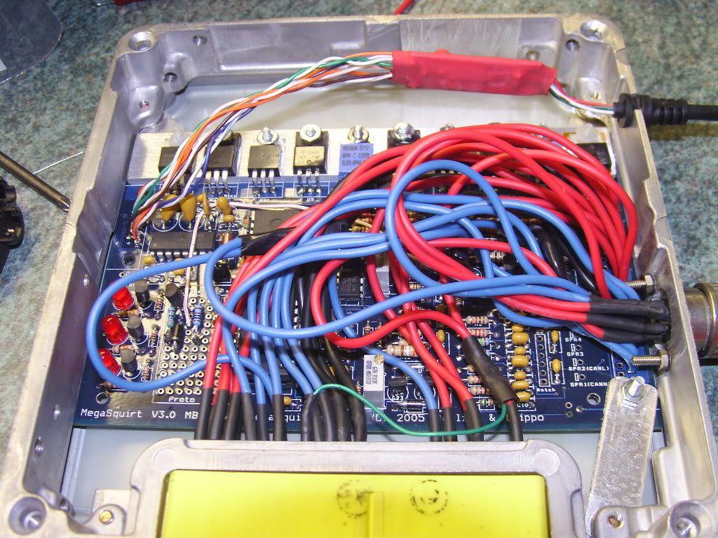
After some epic failing building my megasquirt I now have it running the car. But I think I am now the proud owner of the worst missfire problem in history.
The attatched log shows the classic megasquirt tach dropout that some people have at certain rev ranges sometimes that can be a bit annoying. Mine starts at idle and stays till redline. Oh and its all the time
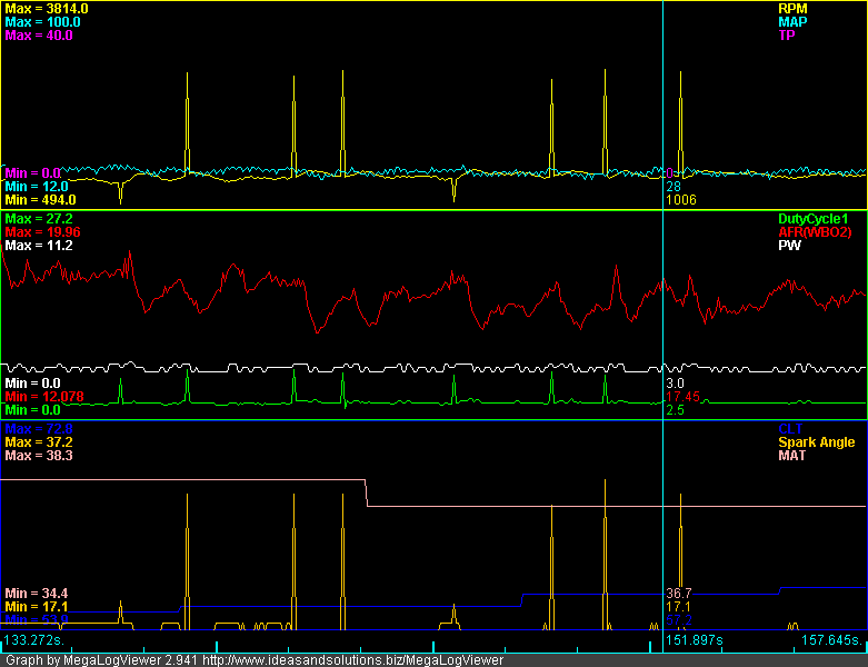
Now Joe thinks that I may have a noisy signal from my CAS similar to the one that caused him to kick his to the curb in favour of a crank wheel (something I am seriously considering) I have just hooked up my simplistic computer scope directly to my CAS and had a look at my signals.
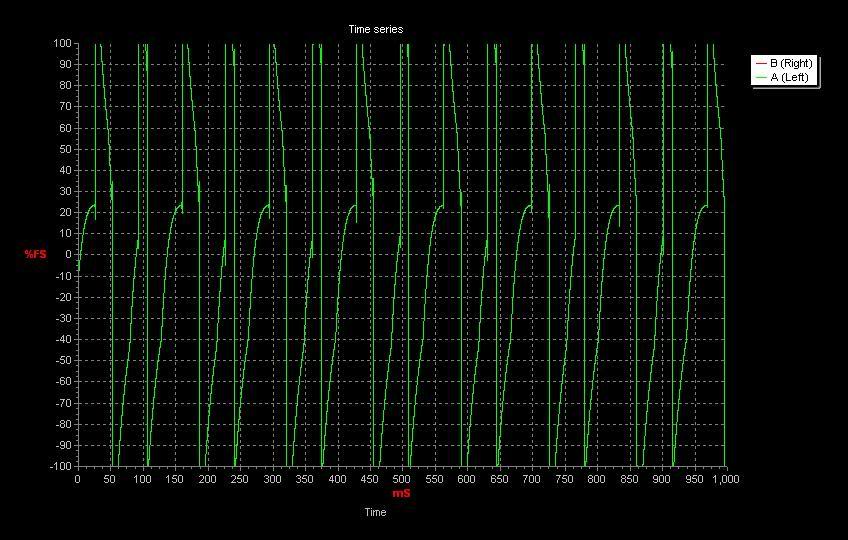


Now I'm not sure I can see anything wrong with them.
I followed Brains how-to to the letter with regards to mods.
Can someone who is far cleverer than me please suggest where I may have gone wrong in my build?
Also I have heard something about a "dave cap" that really helps sort out tach spikes but I cant find much info on it ( I think its either been incorporated into the V3 board or dropped) any one learn me on this?
If any more scoping is required please let me know, I think it might be a good idea to check the signal just as it enters the MS to make sure the wiring isn't horrid.
Thanks in advance
Yours faithfully
Hoping not to be down the scrapyard looking for a 36-1 wheel
Tom
The attatched log shows the classic megasquirt tach dropout that some people have at certain rev ranges sometimes that can be a bit annoying. Mine starts at idle and stays till redline. Oh and its all the time
Now Joe thinks that I may have a noisy signal from my CAS similar to the one that caused him to kick his to the curb in favour of a crank wheel (something I am seriously considering) I have just hooked up my simplistic computer scope directly to my CAS and had a look at my signals.
Now I'm not sure I can see anything wrong with them.
I followed Brains how-to to the letter with regards to mods.
Can someone who is far cleverer than me please suggest where I may have gone wrong in my build?
Also I have heard something about a "dave cap" that really helps sort out tach spikes but I cant find much info on it ( I think its either been incorporated into the V3 board or dropped) any one learn me on this?
If any more scoping is required please let me know, I think it might be a good idea to check the signal just as it enters the MS to make sure the wiring isn't horrid.
Thanks in advance
Yours faithfully
Hoping not to be down the scrapyard looking for a 36-1 wheel
Tom

Reply
 0
0

0
 08-01-2008, 05:07 AM
#4
Junior Member
Thread Starter
iTrader: (1)
Join Date: Apr 2008
Location: Bristol
Posts: 439
Total Cats: 0
I found this on the MS2extra hardware manual, I assume it will be the same for MS1 extra. Any chance that this would work any better than the DIY mods? Its got a little more filtering by the looks of it in the form of C12. 
The second input is also a little safer with the opto isolator.
The second input is also a little safer with the opto isolator.
Last edited by Duckie_uk; 08-01-2008 at 06:43 AM.
Reply
0
0
08-01-2008, 08:14 AM
#5
Junior Member
Thread Starter
iTrader: (1)
Join Date: Apr 2008
Location: Bristol
Posts: 439
Total Cats: 0
I found these in the MS1extra manual for 4G63 which should be identical to the miata setup.
They look inverted to the ones for MS2 I assume this is something to do with rising vs falling edge triggering.
The really interesting this is that Jerry from DIY cooked them up but they are different to the ones on the DIY site.
They look inverted to the ones for MS2 I assume this is something to do with rising vs falling edge triggering.
The really interesting this is that Jerry from DIY cooked them up but they are different to the ones on the DIY site.
Reply
0
0
 08-01-2008, 12:08 PM
#8
Junior Member
Thread Starter
iTrader: (1)
Join Date: Apr 2008
Location: Bristol
Posts: 439
Total Cats: 0
I have Just tried several values for C12 which the assembly guide says might help with tach problems. No improvement 
I cannot believe that there is something wrong with the car because it runs fine with the stock ECU, there must be something that I have cocked up in building my MS.
So far all I have done is make my car un-drivable
I cannot believe that there is something wrong with the car because it runs fine with the stock ECU, there must be something that I have cocked up in building my MS.
So far all I have done is make my car un-drivable
Reply
0
0
08-02-2008, 09:57 AM
#11
Junior Member
Thread Starter
iTrader: (1)
Join Date: Apr 2008
Location: Bristol
Posts: 439
Total Cats: 0
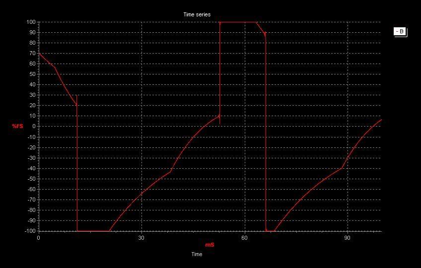
I took these from the output of the opto circuit on the MS. Hopefully a freind is going to bring his car around so that I can test my MS with a different CAS.
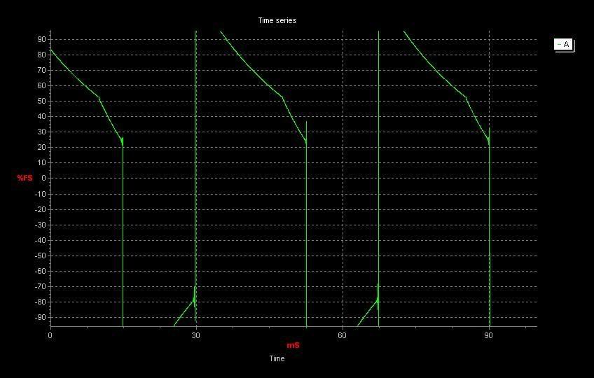
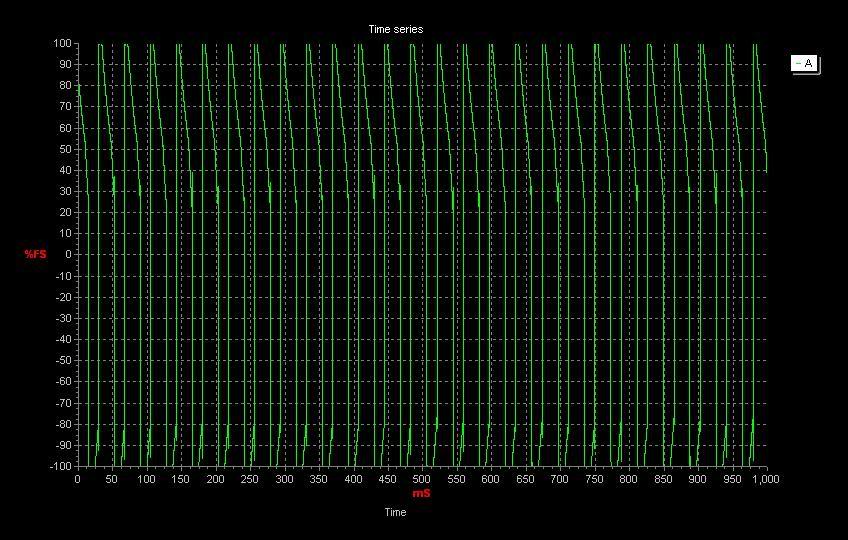
Next step I think is to try Abes input circuit.
Next step I think is to try Abes input circuit.
Reply
0
0
08-02-2008, 11:28 AM
#12

You do that first, mate. Easier than screwing around with caps and stuff. Unless you want to.
Cheap source of CAS is most small mazda engines from the 90's. AFAIK, the 121 engine (was sold in the UK, I think) has the same CAS with a different hole pattern (4/1 instead of 4/2).
Reply
0
0
08-02-2008, 01:07 PM
#13
Junior Member
Thread Starter
iTrader: (1)
Join Date: Apr 2008
Location: Bristol
Posts: 439
Total Cats: 0
Well my buddy poped round the the MX-5 that he borrowed from his girlfreind. Two letters N B. Do'h should have asked that really but never mind. Now to find someone else who has a MX-5 in my network of freinds.
I spent all morning in the scrapyard looking for either a CAS or a 36-1 crank wheel. No luck on either. Found a few SOHC Mitsubishis with the wrong CAS. I cannot believe that of all the fords I found all were either Zetec or CVH without Crank wheels!!
I found a CAS on the web for ~$80 good price? anyone have one I can buy for less?
Reply
0
0
08-03-2008, 04:11 PM
#14
Junior Member
Thread Starter
iTrader: (1)
Join Date: Apr 2008
Location: Bristol
Posts: 439
Total Cats: 0
Well I think I finally killed it. I built a copy of Abe's circuit on breadboard and tried to fire her up. No dice. And now I can't get megatune to connect to the MS. Tomorow I'm going to see If I can ressurect the MS.
I built the circuit exactly to Abe's diagram and supplied the LM393 with 5V on Vcc and GND on Vdd was that right? How do I test it outside of the MS? Any help would be greatly appreciated because I'm very close to throwing the whole lot in the bin
I built the circuit exactly to Abe's diagram and supplied the LM393 with 5V on Vcc and GND on Vdd was that right? How do I test it outside of the MS? Any help would be greatly appreciated because I'm very close to throwing the whole lot in the bin
Reply
0
0
08-04-2008, 12:06 PM
#15
Junior Member
Thread Starter
iTrader: (1)
Join Date: Apr 2008
Location: Bristol
Posts: 439
Total Cats: 0
Well MS is running again  yay
yay
Now just back to sorting out the missfire.
I'm beginning to think that perhaps there is something on the engine that is causing the spikes, (Didn't Abe's problem turn out to be VICS?) Could the FIDLE valve be causing interference? or perhaps having the LC-1 grounded to the MS board? That was confusing because Innovate say ground everything in one place to avoid ground loops and other prople say the heater ground is noisy and keep it the hell away from everything else
yay Now just back to sorting out the missfire.
I'm beginning to think that perhaps there is something on the engine that is causing the spikes, (Didn't Abe's problem turn out to be VICS?) Could the FIDLE valve be causing interference? or perhaps having the LC-1 grounded to the MS board? That was confusing because Innovate say ground everything in one place to avoid ground loops and other prople say the heater ground is noisy and keep it the hell away from everything else
Reply
0
0
 08-04-2008, 05:19 PM
#18
Junior Member
Thread Starter
iTrader: (1)
Join Date: Apr 2008
Location: Bristol
Posts: 439
Total Cats: 0
Matt, I bring all of the LC1 wires into my case through a separate connector and then send both grounds to one of the spare ground holes where my DB37 should be, the signal also goes directly to the hole in the board and I share the 12vfeed from my MAZDA connector between the MS, LC1 and a 1k resistor to pull up the feed for my tach.
Jason, Our CAS has "active circuitry" inside it which turns the hall signal into a fuckoff 5V square wave. It doesn't have any shielding as far as I know and it only has one ground which goes to the head and is on the same wire as one of the MS grounds. As for the sensor ground pin I think MS just uses the one ground plane, Matt?
Jason, Our CAS has "active circuitry" inside it which turns the hall signal into a fuckoff 5V square wave. It doesn't have any shielding as far as I know and it only has one ground which goes to the head and is on the same wire as one of the MS grounds. As for the sensor ground pin I think MS just uses the one ground plane, Matt?
Reply
0
0
08-04-2008, 10:37 PM
#19
Boost Pope


iTrader: (8)
Join Date: Sep 2005
Location: Chicago. (The less-murder part.)
Posts: 33,052
Total Cats: 6,615
I wouldn't completely discount the CAS. For a month or two after I installed my MS, I tried moving heaven and earth to get rid of the damn misfire. Built all manner of input circuits, and nothing worked. Finally built the 36-1 setup and it's been rock-solid since.
I'm not saying you need to go out and fab a 36-1 setup, only that it is possible for a CAS to go bad in such a way that the stock ECU can still tolerate it but the MS does not. My guess is that the stocker did some fancy software debouncing that MS does not support.
Apparently I'm not the only one who has had this experience. One or two other folks also started with a funky CAS that worked fine on a stock ECU but not on MS. Simply installing a different (identical) CAS solved the problem. I know you're having trouble finding one, but don't give up and do anything drastic until you've had a chance to try one.
Reply
0
0
08-05-2008, 04:30 AM
#20
Junior Member
Thread Starter
iTrader: (1)
Join Date: Apr 2008
Location: Bristol
Posts: 439
Total Cats: 0
ATM I'm going to shelf the project for a month, I am soon to be moving into a new house and going back to college so I really need to have a car that works, I'm leaving everything installed but just switching the MS for the stocker (joys of PNP).
I'll still be on the hunt for a CAS to try. I've spent days in the scrapyard looking for a suitable candidate but I have learnt two things. 1 All UK fords with EDIS used notches in the flywheel and didn't have a ring on the crank pully. 2. Any and all Japanese cars are either picked clean or not suitable (all wrecked miatas are bought and broken by specialists ). To add insult to injury, while scouting around I saw on the floor the stainless disk from an optical CAS!! If anyone could find it in their heart to pick me up a CAS when they're next in a junkers then they will have my eternal gratitude (and some $$ in a paypal account. PM me if you think you can accommodate).
I actually have a 60-2 crank pully and VR sensor from a Vauxhall that I stripped last year, If I can get round to mounting it (its not a pressed on ring but part of the pully)I'll give it a go, I kept it with the intention of using it with the MS, just not so soon
I'll still be on the hunt for a CAS to try. I've spent days in the scrapyard looking for a suitable candidate but I have learnt two things. 1 All UK fords with EDIS used notches in the flywheel and didn't have a ring on the crank pully. 2. Any and all Japanese cars are either picked clean or not suitable (all wrecked miatas are bought and broken by specialists
). To add insult to injury, while scouting around I saw on the floor the stainless disk from an optical CAS!! If anyone could find it in their heart to pick me up a CAS when they're next in a junkers then they will have my eternal gratitude (and some $$ in a paypal account. PM me if you think you can accommodate).I actually have a 60-2 crank pully and VR sensor from a Vauxhall that I stripped last year, If I can get round to mounting it (its not a pressed on ring but part of the pully)I'll give it a go, I kept it with the intention of using it with the MS, just not so soon
Reply
0
0


