
A Couple Quick Questions Before I build my DIYPNP


Thread Starter
Newb
Joined: Nov 2011
Posts: 20
Total Cats: 0
Been searching for a couple night for info/answers to my questions and couldnt find solid answers. I am going to build my MS unit tonight and want to double check a couple questions that I have.
1. For the seq. injection.. After I solder the 10pin header onto the main board do I have to hook up jumper wires from the main board to the 12v and IAC on the seq inj board? I read your install write up and am a bit confused on that. I know that I have to jump the seq board to inj 3 and 4 in the pronto area which is linked to the 3/4 above inj2 on the edge of the main board.
2. On the 94-95 Miata Jumper Configuration it does not show that you need a IAC pull up. I read in a thread (linked below) that I do need one. Can you confirm that I do?
https://www.miataturbo.net/showthrea...gnition+jumper
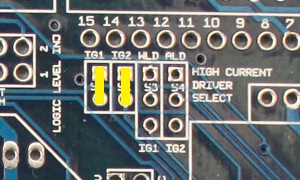
3. For the ignition set up, if I am running the stock ignition/coil set up, do I jump the board like this..?
4. If I am not going to set up my board to knock sensor can I omit the following?
Knock: C3, C4, C5, Q10, R22, R23, R24, R25, R26, R27, R28, U3, U4
Any/all help is greatly appreciated. Thanks!
1. For the seq. injection.. After I solder the 10pin header onto the main board do I have to hook up jumper wires from the main board to the 12v and IAC on the seq inj board? I read your install write up and am a bit confused on that. I know that I have to jump the seq board to inj 3 and 4 in the pronto area which is linked to the 3/4 above inj2 on the edge of the main board.
2. On the 94-95 Miata Jumper Configuration it does not show that you need a IAC pull up. I read in a thread (linked below) that I do need one. Can you confirm that I do?
https://www.miataturbo.net/showthrea...gnition+jumper
3. For the ignition set up, if I am running the stock ignition/coil set up, do I jump the board like this..?
4. If I am not going to set up my board to knock sensor can I omit the following?
Knock: C3, C4, C5, Q10, R22, R23, R24, R25, R26, R27, R28, U3, U4
Any/all help is greatly appreciated. Thanks!
Reply
 0
0

0

Junior Member
Joined: Nov 2009
Posts: 109
Total Cats: 2
From: Dumfries, VA
1. I ran my outputs directly to injectors 2 and 4, not 3 and 4 on the output board. Make sure you get it right. AEM's EMS publishes the correct injector locations on the harness. I verified them. Check this to confirm cylinders 2 and 4 not 3 and 4 and correct order: http://www.diyautotune.com/diypnp/docs/sequential.html
2-4. Can't remember - sorry and I've got a 96.
2-4. Can't remember - sorry and I've got a 96.
Reply
0
0


Not populated for Miata. They are only used for adjustment of a VR type cam signal.

Reply
0
0
1. yes, you'll wire the two outputs holes labeled 3 & 4, to the match holes right near the module. then youll wire the 3 and 4 hole near the other two inj outputs to th3 connector board.
2. not a pull up, but a diode, bottom right corner of the board.
3. no, on the bottom right corner where the pullups are, you'll jump op- to 12v and vr2 to 5v with the spare 470ohm resistors.
just follow this:
http://www.diyautotune.com/diypnp/ap...5-18bp-mt.html
2. not a pull up, but a diode, bottom right corner of the board.
3. no, on the bottom right corner where the pullups are, you'll jump op- to 12v and vr2 to 5v with the spare 470ohm resistors.
just follow this:
http://www.diyautotune.com/diypnp/ap...5-18bp-mt.html
Reply
0
0
Thread Starter
Newb
Joined: Nov 2011
Posts: 20
Total Cats: 0
Got mine all done up. Last thing to do is to wire up my lc1 to the mega squirt. I can't find a thread that clearly describes how to install it in conjunction with my MS. anyone care to link me to an install thread or quickly explain how to wire it up so the ms can read it.
Reply
0
0

Thread
Thread Starter
Forum
Replies
Last Post


