When you click on links to various merchants on this site and make a purchase, this can result in this site earning a commission. Affiliate programs and affiliations include, but are not limited to, the eBay Partner Network.
Cranks but doesn't start, runs fine on stock ECU. MS3x, unshielded wires?
Hello everyone,
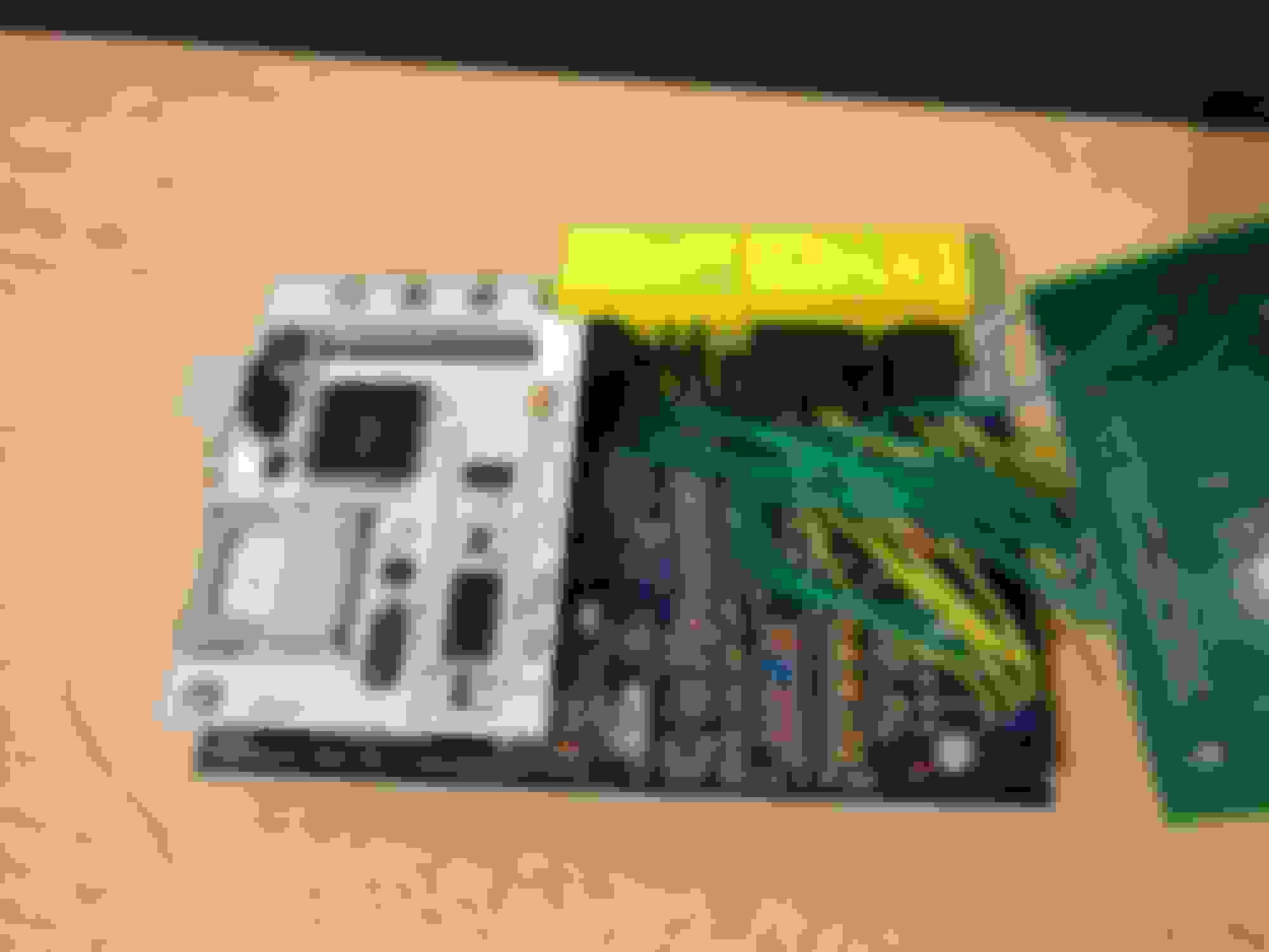
I am trying to learn how to get Megasquirt working as a standalone and am having trouble. This was a DIY unassembled MS3 V3.0 and MS3X kit that I put together following Frank Westfield's guides.
Car is a mostly stock 94 1.8L, only a RB intake right now.
As it stands, I am having an intermittent RPM reading in tunerstudio where the RPM jumps from the regular cranking speed to 0 repeatedly. I don't think this happened my first attempt, so this is a new issue.
Cranks, but won't start, tested with stock ECU and starts right up. I think I can hear the pump prime when I turn the key on with the MS3, a really short sound unless I am confusing it with something else. Adding a bit of throttle also doesn't work, just gets engine to shake a bit.
Using a v3.2.1 basemap, changed settings to my sensors, calibrated TPS, set GM IAT, set coolant temp sensor set to RX7 values, 2490 for both, and narrowband o2 (have a wbo2, waiting until I can get it to idle to install and start tuning).
Now, I'm worried that the cables I used (breadboard jumper wires, ~22 AWG, not labeled) may be having issues due to not being shielded? I checked all my harness connections and they all match the pin-out diagrams for the MS3x, soldering looks fine to me, taking into account my lack of previous experience. Next time I'll make an external harness instead of this mess. At least it will look clean when its in the case. Did I **** up? Attaching msq and log for reference.
Thanks!
Edit: I also checked the the transistors in-case I bridged them with my soldering work, but they seemed to be okay, Q19 had continuity between two of the pins, but I read this is normal and it should a resistance of 1 Ohm, so I think thats okay. MS3 1.4.1 firmware.
Ok, after looking closer and not being dumb i see that you did do those jumpers and the resistor for pullup.
I can tell you one thing for certain, you need to look over ALL of your solders with a magnifying glass. I have recently learned that solder joints may look fine to the naked eye but are a different story when looking close. I also learned that soldering from the top is important as well.
Did you adjust the pots on the resistors per the writeup? If i recall correctly, i had to **** with mine a bit to get it reading correctly. The newer ones dont have a stop or click when at full counter clockwise. R56, R11 and R32.
Yea, I adjusted the pots following the writeup, R56 and R11 adjusted to get a reading between 2.5 And 3 V on each. I didnt adjust R32 however, didnt see anything about that in writeup and it is just full anti clockwise.
I will get a magnifying glass and check out the connections just incase, and I will create a composite log while cranking this afternoon. It's very possible I've made a mistake with the software setup due to my inexperience.
you need to make sure R32 is turned CCW at least 6 turns.
personally i turn R56 7.5 turns CW and R11 3.5 turns CW -- I never measure the voltages, never have issues, but the people who try to hit them always seem to.
Alright so I re-adjusted all pots, and I touched up a few solder connections that seemed sub-par when looking at them under the magnifying glass.
It may be it was quieter outside, but now I am more certain that I hear the fuel pump come on for a second or two to prime, a slight whirring sound if I'm not mistaken, and it also keeps sounding for a split second after I stop cranking, so something may have been fixed.
RPMs are still dropping in and out inside of tunerstudio, and it behaves just as before except now I hear what I think is a relay repeatedly clicking while cranking. Attached the composite log and regular data log files, I hope this is correct.
Last edited by soaps42; Oct 31, 2016 at 07:41 PM.
Reason: Added msl screenshot for convenience
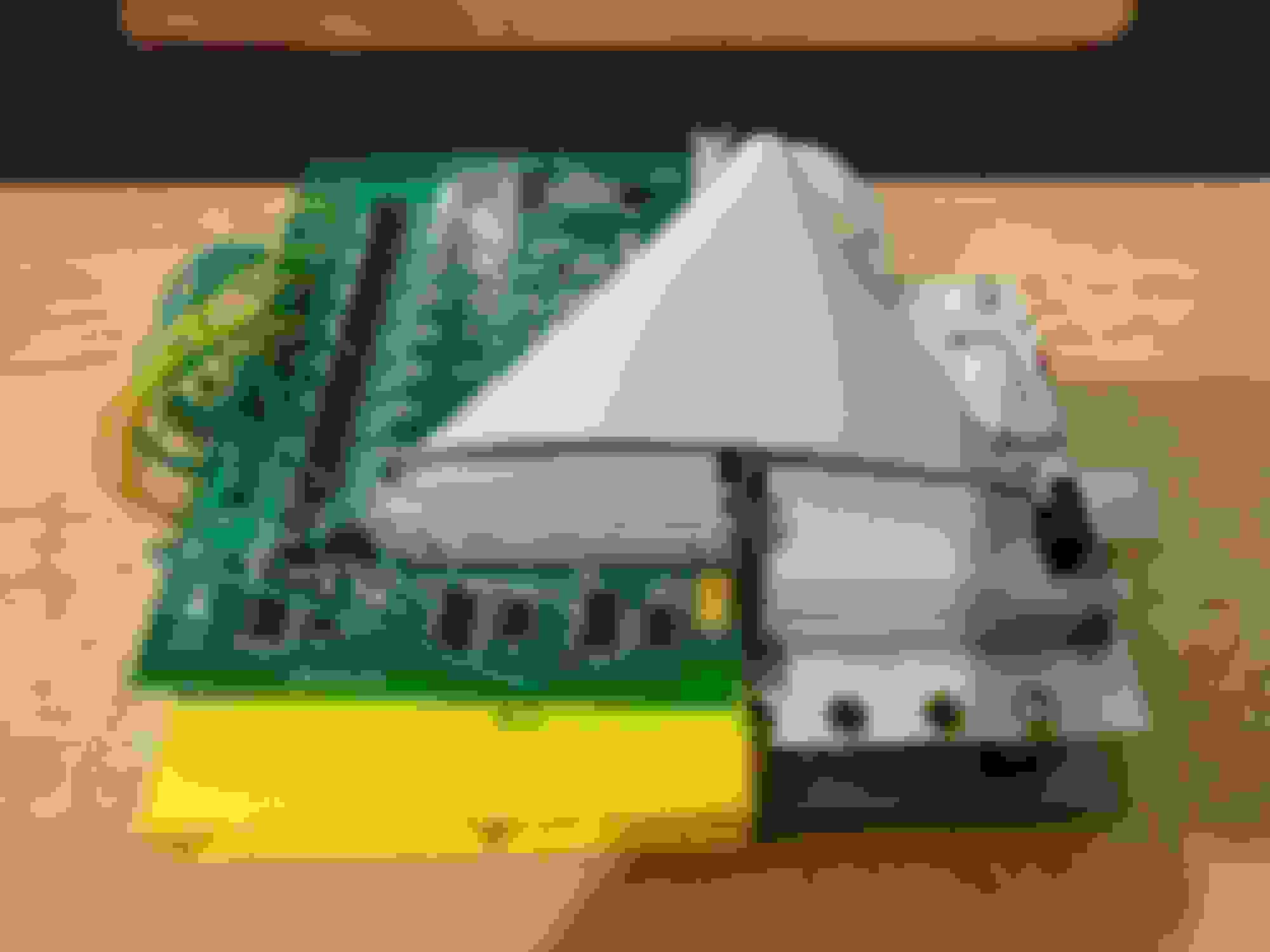
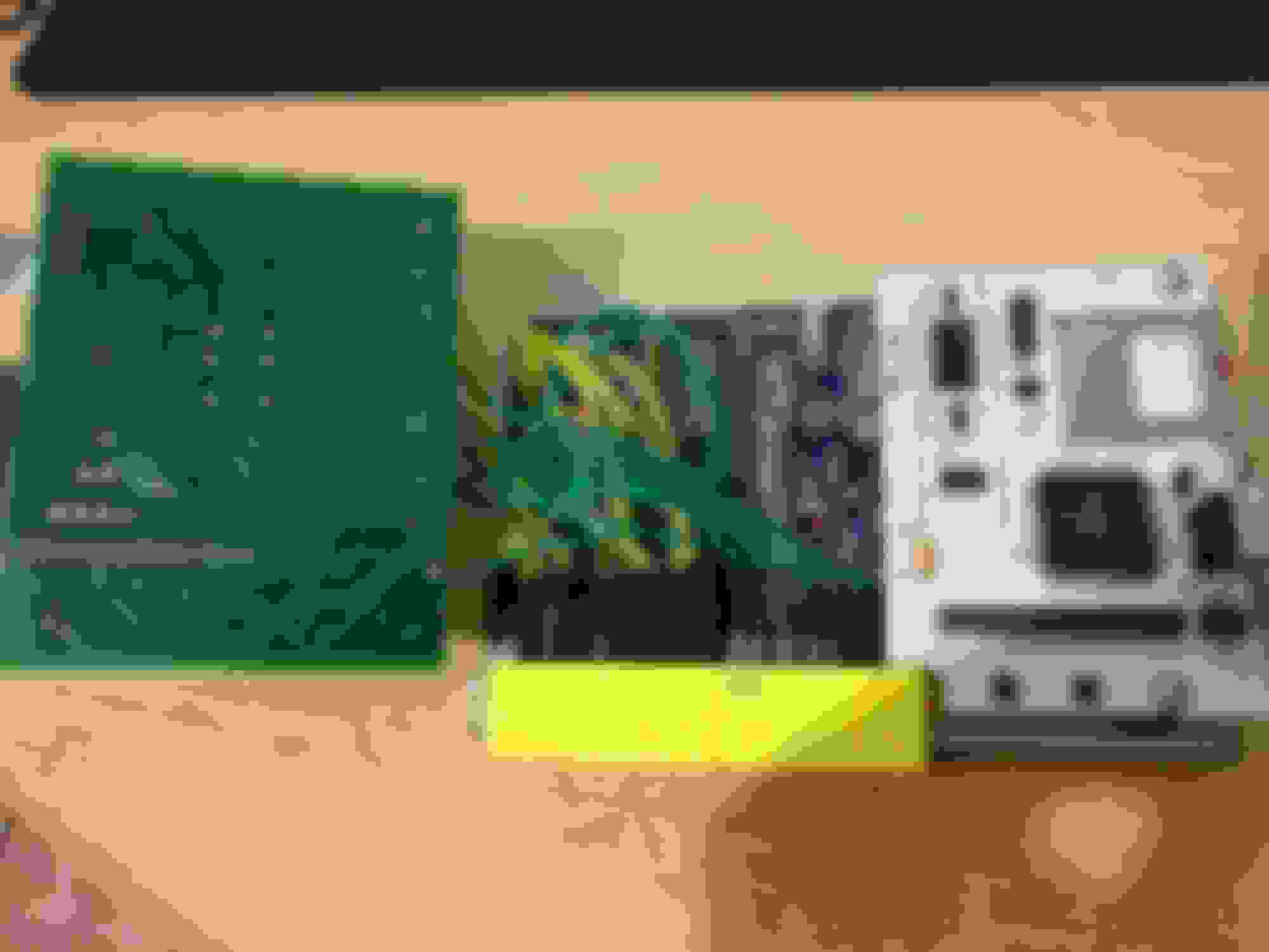
I don't know a lot about Megasquirt, but I know that that's some ***** soldering. Seriously, if you're going to take the time to build a standalone, you should take the extra 1/2 hour it requires to learn how to solder properly. I can pretty much guarantee a few bad joints just in this picture alone.
I don't know a lot about Megasquirt, but I know that that's some ***** soldering. Seriously, if you're going to take the time to build a standalone, you should take the extra 1/2 hour it requires to learn how to solder properly. I can pretty much guarantee a few bad joints just in this picture alone.
Yeah, that is a pic of the worst section by far, and there is some left over solder on some of the empty holes from desoldering the DB37 without a solder sucker or wick, not proud of it, but the ones that are connected do seem to test okay. I may end up soldering both DB37 connectors and making an external harness instead of this method.
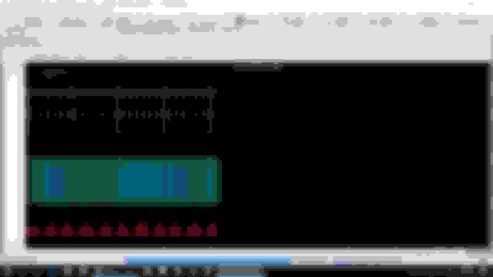
Your composite log shows tons of sync errors. I don't think MS will run an engine without being able to make heads or tails of the crank/cam triggers.
Sorry- I don't know anything about triggering on an NA- I'm NB only- but I'd start looking at triggers.
This is the MS2E v3.3.1a MSPNP2-MM9495 straight from the megasquirt site
Will test switching to rising edge trigger today, I was reading this could fix a lost sync reason 11 and 17 but I was getting 38 and 39 in the logs so I almost overlooked it.
Will test and log again as soon as I get home, and thank you!
Because it looks like I fucked up when searching for the base map in my initial enthusiasm, I will download and ms PNP pro base map and see if I can idle on that. Sorry for the inexperience
Oh.. I thought it would be frowned upon since you didn't build it.
Hey Braineack,
Could I have a base map for a 1994 Miata, 1.8 L stock other than a RB intake? (and a GM IAT from diyautotune)
Thanks
Got home an hour ago and tried it out...
It ******* worked! Im even too happy to feel like a fool for making such a silly mistake initally. All the sync issues are mostly gone and now I know what a composite log actually should look like.
It started right up after some cranking and although it would stall out at first, it started to hold the idle on its own after a while. I'll be installed the wbo2 tomorrow after work/class and start tweaking to get it running smoothly! (and matching the timing ofcourse)
Thanks to all of you that posted, even the guy that talked **** about my soldering lol, really appreciate the help
Thanks for the base tune and the catch Braineack, much appreciated!
Sorry for the wild goose chase!
Edit: Is it worth it to do any further adjustments of the pots for vr circuit? Or is this a "if it aint broke dont fix it" kinda thing?
Last edited by soaps42; Nov 2, 2016 at 01:09 AM.
Reason: Added question


 0
0