When you click on links to various merchants on this site and make a purchase, this can result in this site earning a commission. Affiliate programs and affiliations include, but are not limited to, the eBay Partner Network.
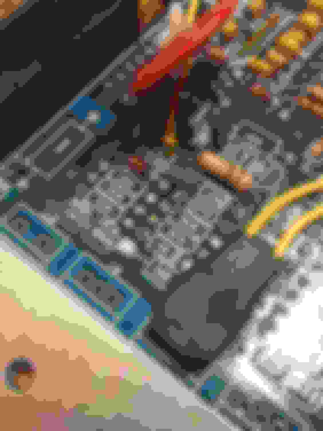
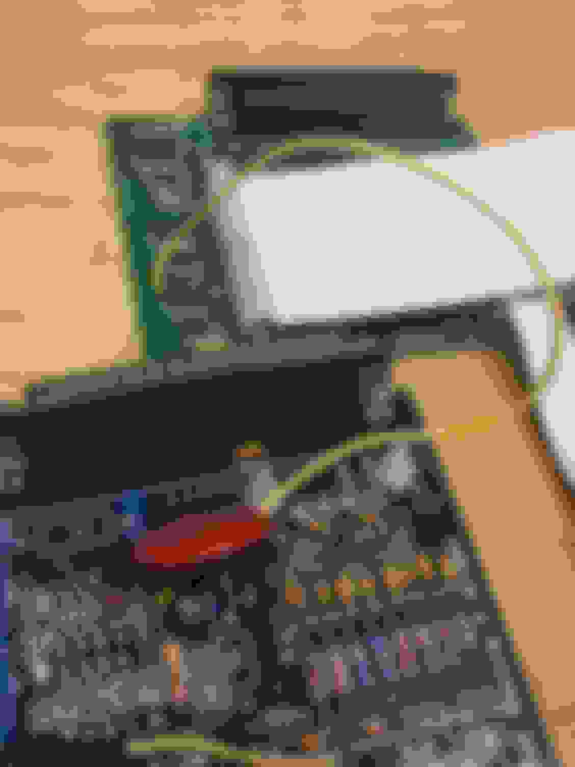
Somerhing nearly nobody does is integrating the ecu connector inside the case. I do because I hate db37 connectors and extra wiring looms. I admit that it gets crowdy inside the case though 😂. The outside and wiring is very neat though.
Hey Frank, do you have a decent photo of how you connect the ECU connector to the board? TIA.
Just a couple of screws. One of the connectors (I believe the 99) resuires no extra holes. For the 2 others, you need to drill a couple of holes, but theres no copper under the heatsink, so no problem at all. The 01 connector requires no cutting of the processor, the 2 others do.
I desolder both db37's and just run the wires directly from the ecu connector to where the db37's were. IMHO by far the best solution, but to each his own.
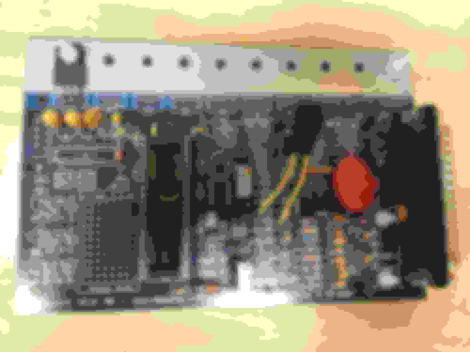
warning warning warning: pics 1 and 3 have the trimmers upside down!
The top trimmer is not needed anyway (replace it with a 100K resistor in the 2 outer holes).
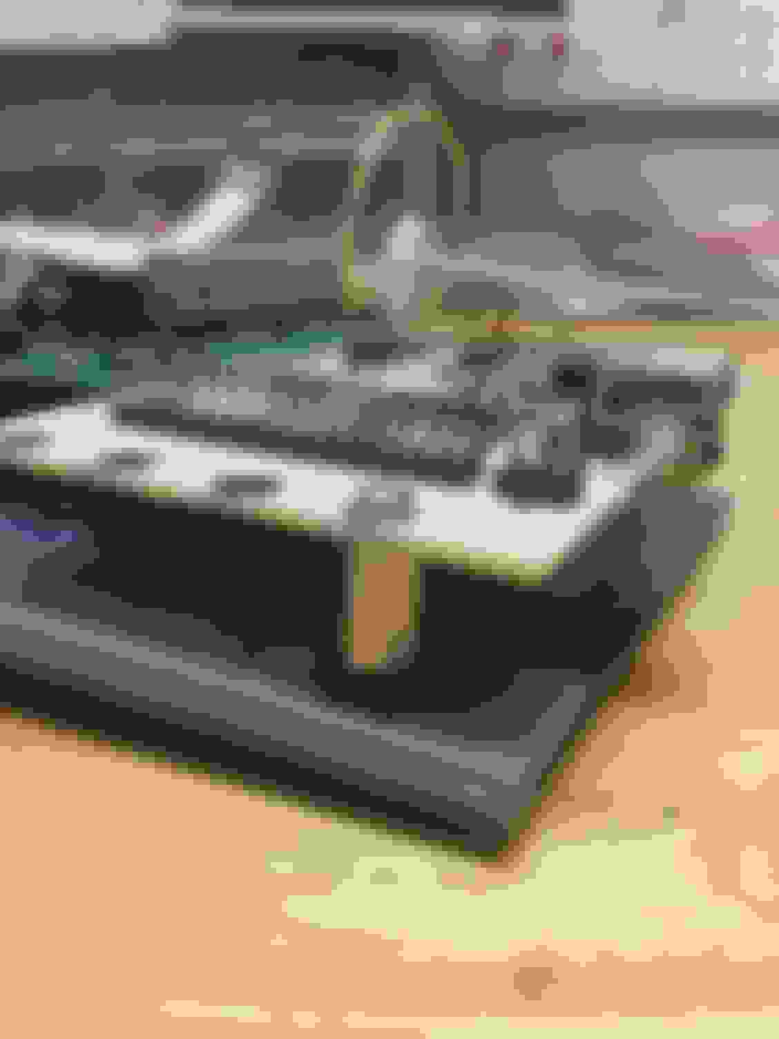
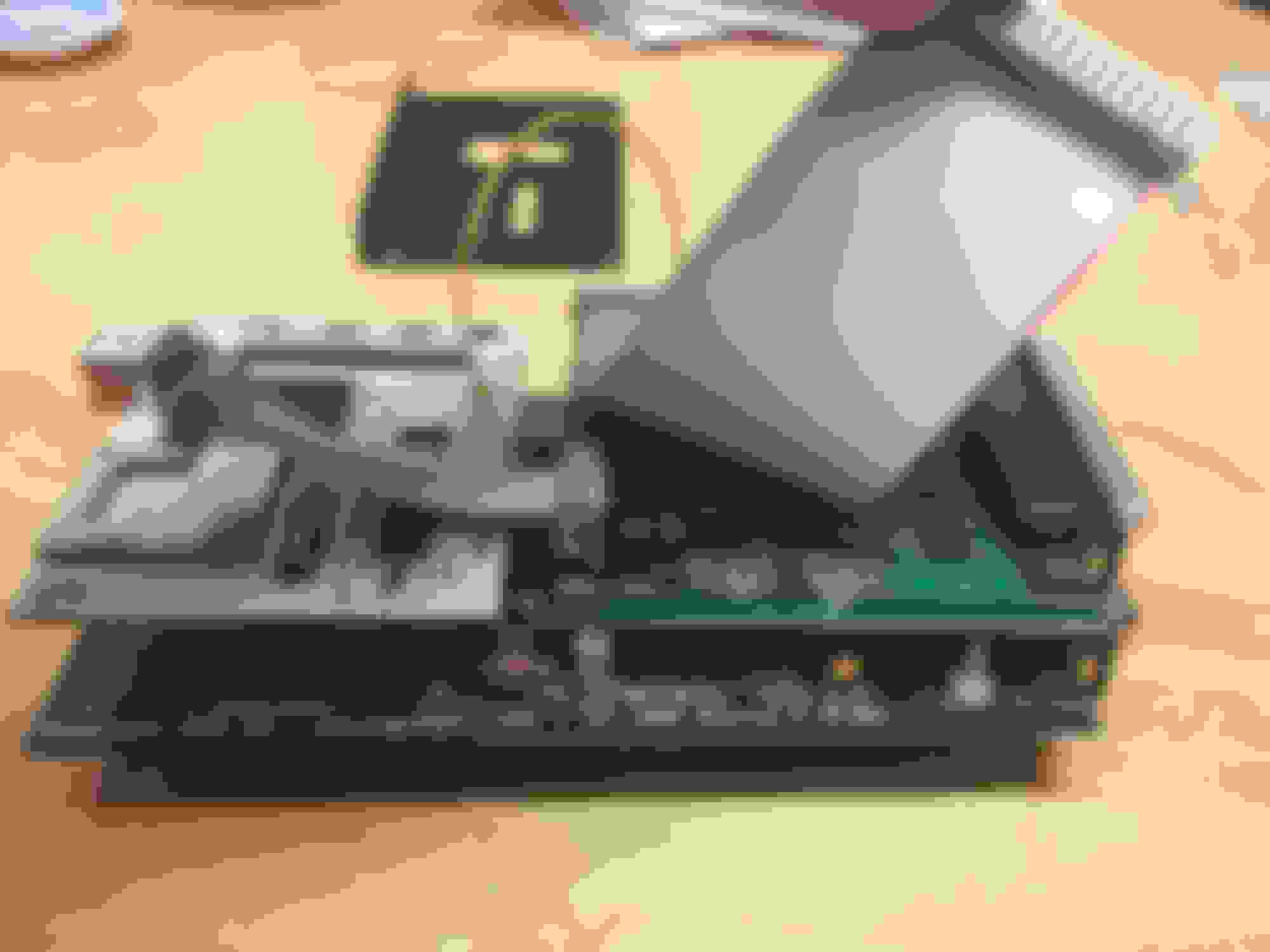
Just finished my box. DIYautotune apparently is close to me here in GA so they got the stuff I ordered yesterday shipped to my house this morning. Very fast.
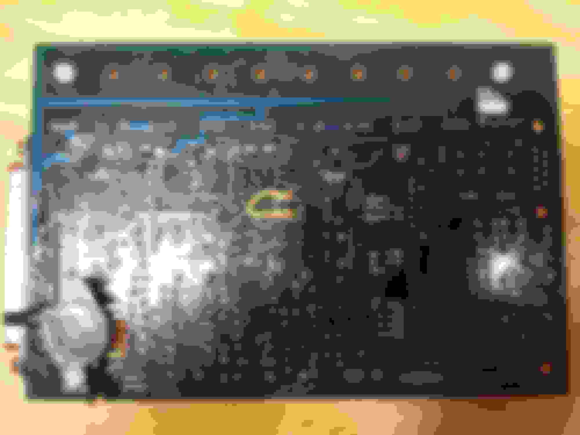
Anything look wrong here? I followed Frank's instructions. Image spam incoming.
(Don't mind the heatshrinked blob in the middle, thats the resistor. I moved it away from the board so it would be easier to solder.)
Screws to the left of the mosfet are for visualization of the screws inside the spacer. Small on the bottom, long on the top.
So now that I have the box built, how do I know it works? I forgot to buy a jimstim and I also followed Frank's instruction on deleting the LED's...
Let's hope this thing isn't dead from static! Any of you ever heard of killing these boards while building them? I grounded myself periodically touching a light switch screw on the wall, but I didn't have a reliable grounding strap.
The MS3x board is just a board with a bunch of output and input circuits on it. A lot of them used to be built on the mainboard. It connects to your ms3 card via 2 ribbon cables. It does not connect to the mainboard (or the main DB37 for that matter at all), think of it as a way to use all of the new ms3 functions that the mainboard doesnt support.
Thank you for the clarification aidan, and thank you Braineack for noticing that. I will put those transistors on immediately.
To load firmware, the MS3 needs a USB connection to a laptop, as well as 12v power input correct?
In order for me to load the firmware while the box is on the bench, can I connect 12v positive and negative to the mainboard DB37? (One on the bottom)
Looks like the positive 12v goes to pin 28 and the negative goes to pin 19.
I ask this because I don't have the mazda ECU connector yet, but would like to load the firmware before I put it in the car.
To the ms3x module.
I still find this the best way to do the wiring. Everything is inside the case and plug and play. Don't understand why people find it silly.
Ok so iv'e been doing this wiring stuff. Frankly, Frank, I find your pinout of the 96-97 harness rather confusing.
This is what is on your website:
The real 96-97 ECU connector looks like this:
I realize that the "Connector 2" section has nothing plugged in. However, the only way to make you're diagram work, assuming you omitted the 2nd connector section, is if you switched the two outer sections of the now 3 section diagram.
Ideally, your diagram should look like this, that is, if you left out the "connector 2" section.
Which brings me to my next problem. The mainboard MS3 DB37 pigtail available from DIYautoTiune do not have wires on pins 8 - 14, so the grounds that fall under those numbers in your diagram will lead to nothing. The wires for the mainboard pigtail run EXACTLY like this:
As far as the chassis grounding wires are concerned on the mainboard, which ones from number 15 - 19 should I plug in to the harness connector?
I would also like some clarification as to what you meant by "crank in" on pin 24 of the mainboard connector. This is the CAS signal correct?
I also am wondering what "OEM NB" does on pin 24 of the mainboard connector. I don't have an NB.
NB is not chassis code, it stands for Narrow Band. As in narrow band oxygen sensor. It clearly tells you in the chassis schematic and the MS schematic that is what the circuit is for.
If you wire it exactly like that pinout says, it will work. not sure why you insist that it is confusing? Seems simple to me and easy to understand.
For the grounds, add them to the connector.
For crank in, did you compare it to the schematics??
Look, the schematic was flipped around and didn't accurately portray the connector it was describing. I don't see how you think that was easy to read in the slightest.
I'm not taking apart the $55 dollar pigtail I bought from the people who designed this system, because some guy who didn't even use the DB37s says some different wire combinations. In fact I bet they all go to the same grounding plane but whatever. I want to hear it from Frank himself.
I am not taking chances with my $600 worth of electronics and I am not "overcomplicating" this. It's already complicated and poorly documented. I'm just trying to make it less so for people who aren't doing this "add a connector to the case" asshattery.
I am one that didnt use the connector in the case and use both db37 to a diybob. I did it exactly as the ms3x wiring pic describes and it works just fine.
1A Exp. 1 White-DarkBlue Main Fan (INJ G)
1B Exp. 4 White-DarkGreen AC Fan (INJ F)
1G Exp. 20 White-Purple AC Out (INJ H)
1K Exp. 30 Gray AC In (Datalog In)
1L Exp. 11 Gray-Red Clutch pedal switch (for launch control)
1M Exp. 28 Gray-Purple VSS (tableswitch in)
*1O Main 17 Black Chassis GND
*1O Main 18 Black Chassis GND
1U Main 37 Violet Fuel Pump
3C Main 23 Pink OEM Narrow Band O2 sensor
3F Main 22 LightBlue Thtottle position Sensor
3G Main 21 Yellow Coolant Temp
3I Main 26 Gray 5v Reference
3K Main 20 Orange Air Intake Temp sensor
3O Main 1 Black(in shielding) Sensor GND
4A Main 2 Shielding Sensor GND
4B Main 29 Red +12v
*4C Main 15 Black Chassis GND
*4C Main 16 Black Chassis GND
*4C Exp. 2 Black Chassis GND
*4C Exp. 3 Black Chassis GND
*4D Exp. 8 Black Chassis GND
*4D Exp. 12 Black Chassis GND
4F Main 24 White(in shielding) Cam Angle Sensor input
4G Exp. 32 DarkGreen tachometer input
4L Exp. 26 LightGreen-Orange tachometer output
4N Exp. 14 Yellow Spark A
4Q Exp. 9 LightGray-Pink Idle Air Control output
4R Exp. 33 Yellow-Orange Spark B
4U Exp. 19 White INJ A (cylinder 1)
4V Exp. 10 White-Pink INJ D (cylinder 2)
4W Exp. 16 White-Orange INJ B (cylinder 3)
4X Exp. 13 White-LightGreen INJ C (cylinder 4)
* denotes multiple wires sharing the same mazda connector pin


 0
0


 and I also followed Frank's instruction on deleting the LED's...
 https://www.miataturbo.net/useful-sa...allation-7000/