
DIY - Raspberry Pi Racedash


Junior Member
Joined: Jun 2015
Posts: 182
Total Cats: 58
From: VIC, Australia
Also if anyone is interested in inputting the fuel level signal into megasquirt you can use the following circuit. I tried just using a 5V pull-up resistor but the tank sender only goes from around 10-120 ohms so it doesn't give you a lot of resolution. This circuit just amplifies the small voltage difference into a much great ~0.5-4V signal.
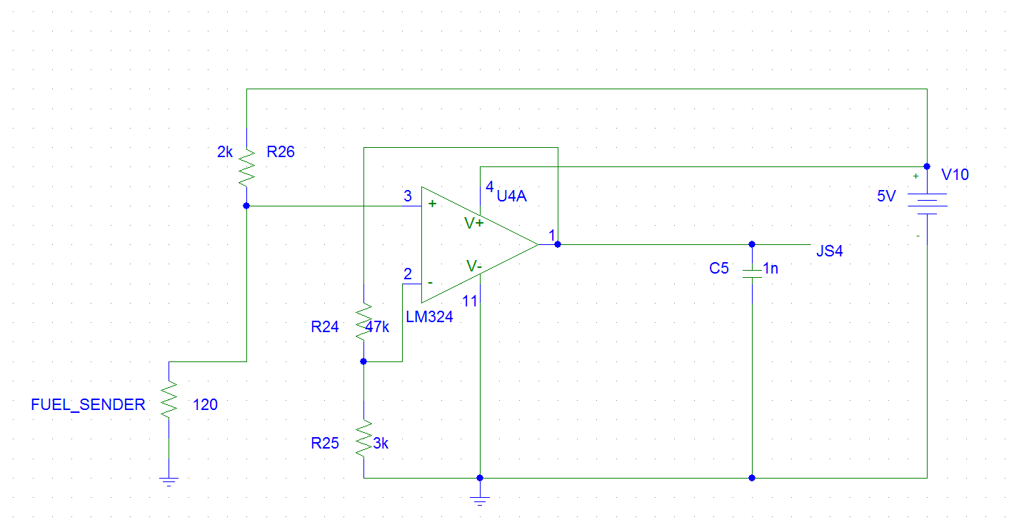
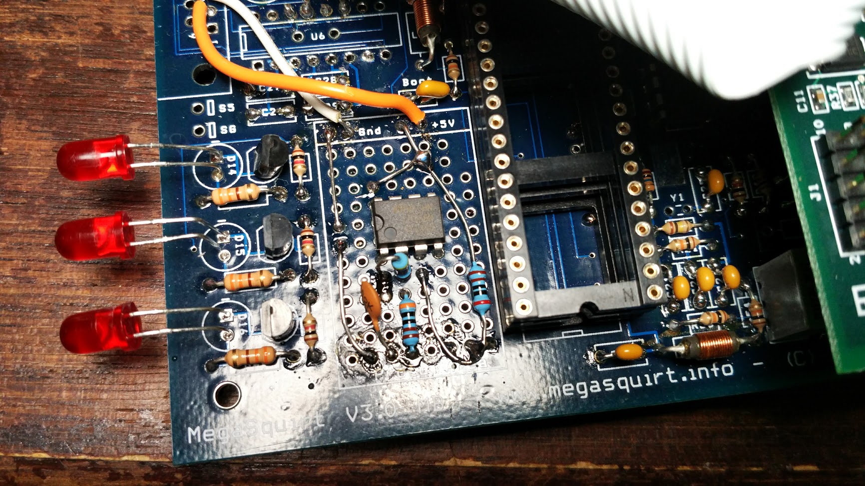
Not the neatest but it works
Not the neatest but it works
Reply
 1
1

1
Junior Member
Joined: Jun 2015
Posts: 182
Total Cats: 58
From: VIC, Australia
Turns out that the fuel sender resistance reading is a bit higher than I thought at the gauge cluster wire so the circuit I posted will need adjusting since it goes out of range and you end up with a fuel level reading that doesn't move till there's about 20L left in the tank. Will come back with the correct values once I do some testing.
Reply
0
0

Thread Starter
Junior Member
Joined: Jul 2013
Posts: 85
Total Cats: 48
From: Norway
Those are great contributions Barton! For a few of the kits I have made I have been using a 90-0ohm fuel gauge. It seems to read pretty accurate.
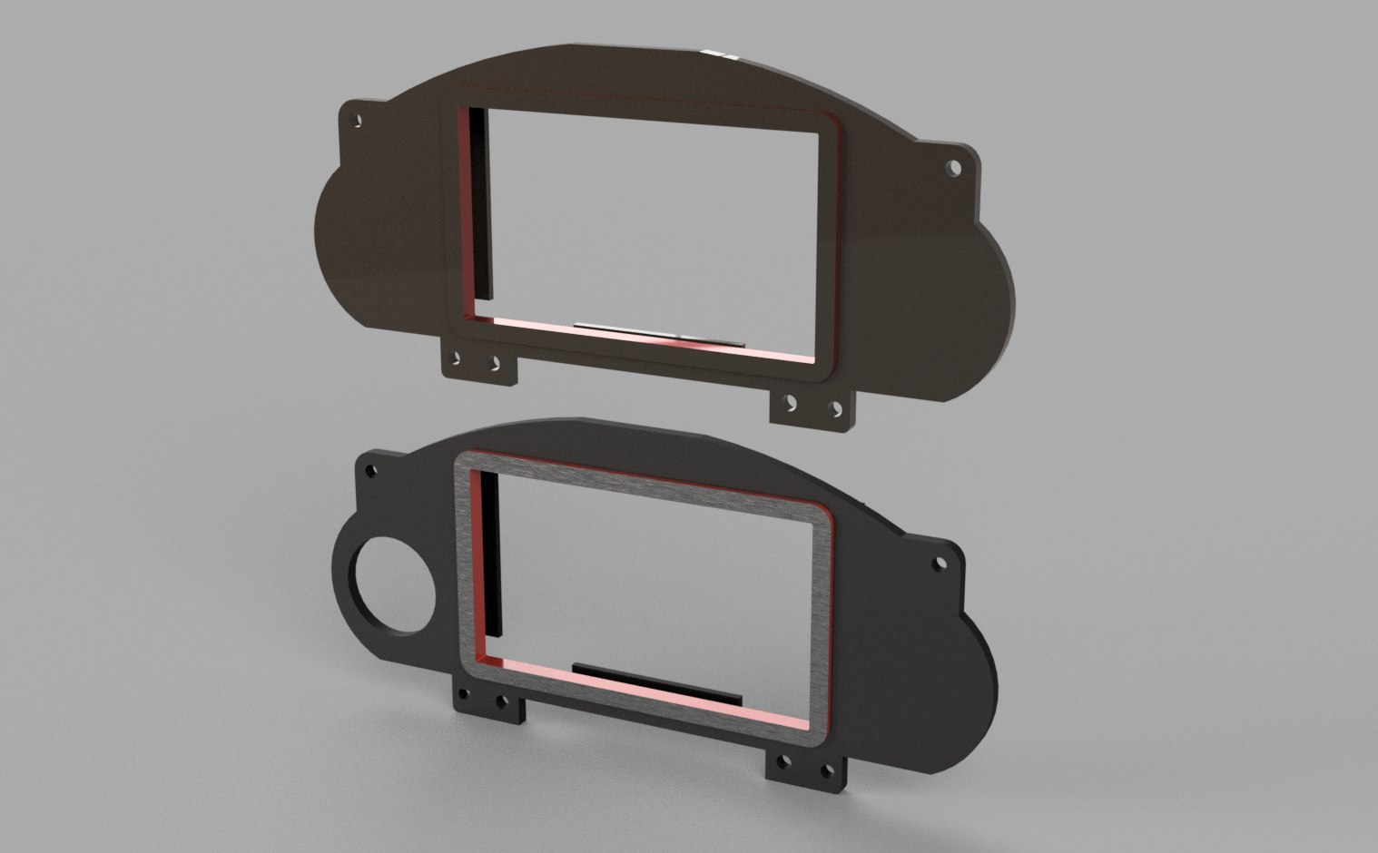
I updated the Thingiverse page with parts for the NB as well. https://www.thingiverse.com/thing:2252864
I updated the Thingiverse page with parts for the NB as well. https://www.thingiverse.com/thing:2252864
Reply
0
0

Turns out that the fuel sender resistance reading is a bit higher than I thought at the gauge cluster wire so the circuit I posted will need adjusting since it goes out of range and you end up with a fuel level reading that doesn't move till there's about 20L left in the tank. Will come back with the correct values once I do some testing.
Reply
0
0

Newb
Joined: Dec 2013
Posts: 28
Total Cats: 2
What would it cost to print one of these dash panels? I'm using a RaceCapture data logger and will be connecting a Raspberry Pi and screen to it rather than an Android tablet. This panel makes my life way easier!
Paul
Paul
Reply
0
0
Junior Member
Joined: Jun 2015
Posts: 182
Total Cats: 58
From: VIC, Australia
Sorry I haven't bothered changing the circuit yet. It functions fine to let me know when I need to fill up and an approximate fuel level but it needs a lot more smoothing of the signal since it moves a fair bit when going around corners etc. I think it really needs some software averaging to take care of that.
A mechanical gauge like what Teejay has been using is the easy solution.
A mechanical gauge like what Teejay has been using is the easy solution.
Reply
0
0
Newb
Joined: Dec 2013
Posts: 28
Total Cats: 2
Sorry I haven't bothered changing the circuit yet. It functions fine to let me know when I need to fill up and an approximate fuel level but it needs a lot more smoothing of the signal since it moves a fair bit when going around corners etc. I think it really needs some software averaging to take care of that.
A mechanical gauge like what Teejay has been using is the easy solution.
A mechanical gauge like what Teejay has been using is the easy solution.
ICM Fuel Sender
Reply
0
0

I'm interested in doing this setup after I get the Megasquirt up and running (within the next 2 months). I do have a few questions. Car is a '91. Cars purpose is weekends/HPDE/nice weather cruiser.
Is this setup to use a GPS based speedometer, or would I have to get an NB VSS? I would like to also be able to have an odometer, but do not view it as a must.
Does this require any wiring into the factory harness other than the fuel gauge, or is everything straight from the ECU? I'd like to run LED's for blinker, high bean indicator, and parking brake light so I figured those were a given. I'm debating picking up an extra factory harness just in case.
How accurate is the 0-90 ohm fuel level gauge compared to stock? I haven't found the resistance values for the stock sending unit. I admittedly haven't looked very hard..
The car will be pretty well stripped of unnecessary circuits depending on how much of a pain in the *** that is as well. Car currently does not have ABS, PS, AC, or power windows. I will be removing the airbag system as well.
Any other tips from those that have this or a similar setup up and running?
Reply
0
0
Junior Member
Joined: Jun 2015
Posts: 182
Total Cats: 58
From: VIC, Australia
You could try this, it's got dampening to prevent gauge bounce, it's what I intend to use for my Arduino.
ICM Fuel Sender
ICM Fuel Sender
Reply
0
0
Junior Member
Joined: Jun 2015
Posts: 182
Total Cats: 58
From: VIC, Australia
I'm interested in doing this setup after I get the Megasquirt up and running (within the next 2 months). I do have a few questions. Car is a '91. Cars purpose is weekends/HPDE/nice weather cruiser.
Is this setup to use a GPS based speedometer, or would I have to get an NB VSS? I would like to also be able to have an odometer, but do not view it as a must.
Does this require any wiring into the factory harness other than the fuel gauge, or is everything straight from the ECU? I'd like to run LED's for blinker, high bean indicator, and parking brake light so I figured those were a given. I'm debating picking up an extra factory harness just in case.
How accurate is the 0-90 ohm fuel level gauge compared to stock? I haven't found the resistance values for the stock sending unit. I admittedly haven't looked very hard..
The car will be pretty well stripped of unnecessary circuits depending on how much of a pain in the *** that is as well. Car currently does not have ABS, PS, AC, or power windows. I will be removing the airbag system as well.
Any other tips from those that have this or a similar setup up and running?
Is this setup to use a GPS based speedometer, or would I have to get an NB VSS? I would like to also be able to have an odometer, but do not view it as a must.
Does this require any wiring into the factory harness other than the fuel gauge, or is everything straight from the ECU? I'd like to run LED's for blinker, high bean indicator, and parking brake light so I figured those were a given. I'm debating picking up an extra factory harness just in case.
How accurate is the 0-90 ohm fuel level gauge compared to stock? I haven't found the resistance values for the stock sending unit. I admittedly haven't looked very hard..
The car will be pretty well stripped of unnecessary circuits depending on how much of a pain in the *** that is as well. Car currently does not have ABS, PS, AC, or power windows. I will be removing the airbag system as well.
Any other tips from those that have this or a similar setup up and running?
I am only using the factory wires for the fuel sender with mine for the moment although I do plan on wiring up LED indicators for the indicators etc.
You just stated the resistance values of the stock sender.... The stock gauge isn't hugely accurate anyway.
Reply
0
0

Newb
Joined: Mar 2011
Posts: 1
Total Cats: 0
Any guidance on getting Tunerstudio installed on Raspbian? I have been working on a project like this, but have very limited experience with Linux. I was able to get everything I want working, except Tunerstudio. =\
Reply
0
0


Junior Member
Joined: Nov 2014
Posts: 128
Total Cats: -15
From: Ypsilanti, MI

Reply
-2
-2
Junior Member
Joined: Jun 2015
Posts: 182
Total Cats: 58
From: VIC, Australia
Just though I'd post some more info on the digital fuel level input. I realised (took me long enough) that the signal return for the fuel sender is grounded at the rear of the chassis with the brake lights, indicators and parkers which means when they're switched on it creates a voltage shift which is why the reading varies so much when they turn on. To get it to work properly you would need to move the signal return to the ECU signal ground.
Reply
0
0


Newb
Joined: Oct 2017
Posts: 23
Total Cats: 2
From: Michigan
Question about the set up of a Pi Dash with an MS3 basic, hoping that this thread would be the right place to post it.
Im planning on using ShadowDash to display on the dash, if my PiDash is pulling data from my MS3, do i need to disconnect the Pi Dash from the MS3 in order to connect to TunerStudio to do actual tuning on my computer? Not sure if i can have both connected simultaneously (one through USB output, one through the serial data output). Or do i need to disconnect the Pi Dash in order to connect to TunerStudio on my computer?
Im planning on using ShadowDash to display on the dash, if my PiDash is pulling data from my MS3, do i need to disconnect the Pi Dash from the MS3 in order to connect to TunerStudio to do actual tuning on my computer? Not sure if i can have both connected simultaneously (one through USB output, one through the serial data output). Or do i need to disconnect the Pi Dash in order to connect to TunerStudio on my computer?
Reply
0
0
Junior Member
Joined: Jun 2015
Posts: 182
Total Cats: 58
From: VIC, Australia
Shadow dash only runs on android though? Is there an android OS available for RaspberryPi now?
As far as I am aware, yes you will need to disconnecet the dash in order to connect another device to the MS.
As far as I am aware, yes you will need to disconnecet the dash in order to connect another device to the MS.
Reply
0
0
Newb
Joined: Oct 2017
Posts: 23
Total Cats: 2
From: Michigan
Sorry about that, will be using a dashboard in Tunerstudio on it. You are correct that Shadow dash runs on Android OS.
That is what i assumed, but wanted to double check if anyone else that has already done this knew for sure. Most likely going to try and use some sort of USB switch to make it cleaner than having to unplug and plug the wires to the different devices when I want to switch.
That is what i assumed, but wanted to double check if anyone else that has already done this knew for sure. Most likely going to try and use some sort of USB switch to make it cleaner than having to unplug and plug the wires to the different devices when I want to switch.
Reply
0
0


