
DIYPNP crank and cam sensor 99/00


Thread Starter
Junior Member
Joined: Nov 2009
Posts: 82
Total Cats: 0
The instructions on the DIY site don't say which two connections are the crank and the cam sensor.
http://www.diyautotune.com/diypnp/ap...0-18bp-mt.html
Any idea where the cam and crank are hooked up to the DIYPNP?
http://www.diyautotune.com/diypnp/ap...0-18bp-mt.html
Any idea where the cam and crank are hooked up to the DIYPNP?
Reply
 0
0

0


Joined: Sep 2005
Posts: 34,402
Total Cats: 7,523
From: Chicago. (The less-murder part.)
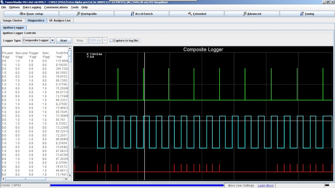
You asked what they look like on a scope, not what they look like in TunerStudio's composite logger. When viewed on a scope, the cam and crank sensors of any 1999 through 2005 Miata look like the upper pair of traces in the image I posted.
I've never actually used TS's tooth logger, so I'm afraid I can't tell you how to interpret it.
I've never actually used TS's tooth logger, so I'm afraid I can't tell you how to interpret it.
Reply
0
0
Joined: Sep 2005
Posts: 34,402
Total Cats: 7,523
From: Chicago. (The less-murder part.)
Since nobody else has chimed in yet, all I can say is "I don't know."
I tried using the tooth logger once, back when I was having a misfire that I suspected (and later proved, by elimination) was caused by dropouts in my crank sensor reading. But since I have an MS1, the tooth logger proved to be pretty much useless in troubleshooting that problem owing to the MS1's inability hold more than 93 samples at a time.
So it's all Greek to me.
Reply
0
0

Joined: Sep 2005
Posts: 34,402
Total Cats: 7,523
From: Chicago. (The less-murder part.)
I'm not sure what any of the lines mean. Neither the green line nor the blue line actually depict the raw crank sensor- they're both showing evenly-spaced events, whereas neither crank nor the cam sensor are evenly spaced. The four crank teeth are arranged in two groups such that the gaps are roughly 70� - 110� - 70� - 110�.
Since he's looking at the "composite logger" rather than the "tooth logger", I simply haven't a clue what's actually being shown. It bears no relation to an NB crank or cam signal that I can see.
Since he's looking at the "composite logger" rather than the "tooth logger", I simply haven't a clue what's actually being shown. It bears no relation to an NB crank or cam signal that I can see.
Reply
0
0

Joined: Sep 2005
Posts: 34,402
Total Cats: 7,523
From: Chicago. (The less-murder part.)
One other thing:
It's actually quite easy. Point a digital camera at the screen and take a picture. Depending on your scope's persistence, sweep time and beam intensity, you may need to play with the camera's shutter speed to get a clean shot. Back in ye olde' times, there were special fixtures for doing precisely this with Polaroid cameras.
It's actually quite easy. Point a digital camera at the screen and take a picture. Depending on your scope's persistence, sweep time and beam intensity, you may need to play with the camera's shutter speed to get a clean shot. Back in ye olde' times, there were special fixtures for doing precisely this with Polaroid cameras.
Reply
0
0
Joined: Sep 2005
Posts: 34,402
Total Cats: 7,523
From: Chicago. (The less-murder part.)
I don't even mean the red. You could take that trace away and the green & blue traces would still look absolutely nothing at all like an NB's crank and cam sensor signals.
Again, I'm making assumptions here, as I don't have any first-hand knowledge of how the composite logger works, but it's certainly not display anything that, to my eyes, looks like a Miata crank/cam signal.
Again, I'm making assumptions here, as I don't have any first-hand knowledge of how the composite logger works, but it's certainly not display anything that, to my eyes, looks like a Miata crank/cam signal.
Reply
0
0

Something is wrong. This what NB triggers look like on a composite log:
(note the similarity to Joe's scope capture)

(note the similarity to Joe's scope capture)
Reply
0
0
How are you generating the log that you posted? It's what I would expect from a B6T 4/1 CAS. Looks nothing like a Miata wave form.
Reply
0
0

Senior Member
Joined: Nov 2007
Posts: 999
Total Cats: 73
From: Belgium
that's weird Ben, my '00 looks like this.
Notice my cam signal is upside down. Also each time there's a cam trigger, I get that same trigger on the crank signal. Those are not there in your traces it seems. Could you zoom in a bit further on your signal?
According to Joe's capture they shouldn't be there. The car runs fine although it does take a long time to sync (5-6 full cycles).
Any ideas what could be causing this? I'm using Joe's input circuits on a V3 board.
Last edited by WestfieldMX5; Sep 27, 2010 at 02:17 PM.
Reply
0
0


