DIYPNP install: inital tuning


 10-10-2011, 01:25 AM
#402
Junior Member
Thread Starter

Join Date: Jun 2007
Posts: 411
Total Cats: 0
It still needs fine tuning, but right off the bat it works very well!
Keep in mind I like a relatively aggressive PID, so I still modified the ini to allow D greater than 200. Having said that...I ended up reducing the PID values massively! I...just don't need them too high anymore.
I ended up with P30 I40 D200 (amazingly sane values). The D is still 200 to combat the slight dips from electrical loads (SPAL fans). I also reduced the effect of PID on valve duty by increasing the max RPM from 1600 to 1800.
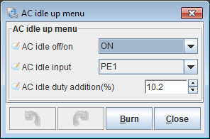
The AC idle up (pinch me ) is triggered by PE1 and is set to increase idle duty by 13.7%. You can clearly see the point where it kicks in. Any higher and the RPM can't come down to target and you feel the code working to bring it down. So yes I do believe an RPM target adder would go well with this mod.
Right now I have not rewired the car, so I am still running the AC signal through the external time delay relay. So I can't confirm the operation of the time delay using status 4 just yet. The current time delay ~ 1 sec is already too much (RPM rises), I believe it will be best at ~100-200ms. With the correct delay set, AC engagement should be near seamless.
Keep in mind I like a relatively aggressive PID, so I still modified the ini to allow D greater than 200. Having said that...I ended up reducing the PID values massively! I...just don't need them too high anymore.
I ended up with P30 I40 D200 (amazingly sane values). The D is still 200 to combat the slight dips from electrical loads (SPAL fans). I also reduced the effect of PID on valve duty by increasing the max RPM from 1600 to 1800.
The AC idle up (pinch me
) is triggered by PE1 and is set to increase idle duty by 13.7%. You can clearly see the point where it kicks in. Any higher and the RPM can't come down to target and you feel the code working to bring it down. So yes I do believe an RPM target adder would go well with this mod. Right now I have not rewired the car, so I am still running the AC signal through the external time delay relay. So I can't confirm the operation of the time delay using status 4 just yet. The current time delay ~ 1 sec is already too much (RPM rises), I believe it will be best at ~100-200ms. With the correct delay set, AC engagement should be near seamless.

Reply
 0
0

0
10-10-2011, 03:51 AM
#403
Originally Posted by Greg G
It still needs fine tuning, but right off the bat it works very well!
Originally Posted by Greg G
The AC idle up (pinch me ) is triggered by PE1 and is set to increase idle duty by 13.7%. You can clearly see the point where it kicks in. Any higher and the RPM can't come down to target and you feel the code working to bring it down. So yes I do believe an RPM target adder would go well with this mod.
) is triggered by PE1 and is set to increase idle duty by 13.7%. You can clearly see the point where it kicks in. Any higher and the RPM can't come down to target and you feel the code working to bring it down. So yes I do believe an RPM target adder would go well with this mod.
Originally Posted by Greg G
Right now I have not rewired the car, so I am still running the AC signal through the external time delay relay. So I can't confirm the operation of the time delay using status 4 just yet. The current time delay ~ 1 sec is already too much (RPM rises), I believe it will be best at ~100-200ms. With the correct delay set, AC engagement should be near seamless.

Reply
0
0
10-10-2011, 04:27 AM
#405
Elite Member
iTrader: (1)

Join Date: Jun 2006
Location: Warrington/Birmingham
Posts: 2,642
Total Cats: 42
Seeing as you've not had to remove anything, and the devs haven't had to impart any effort to implement it, hopefully your code can be integrated into the main release code, so we get to keep A/C idle up & get the latest bug fixes and code improvements.
Reply
0
0
10-10-2011, 04:54 AM
#406
Junior Member
Thread Starter
Join Date: Jun 2007
Posts: 411
Total Cats: 0
While we're at it, may I point out this thread? 
http://www.msextra.com/forums/viewto...?f=125&t=37976
http://www.msextra.com/forums/viewto...?f=125&t=37976
Reply
0
0
10-10-2011, 05:11 AM
#407
While we're at it, may I point out this thread?
http://www.msextra.com/forums/viewto...?f=125&t=37976
http://www.msextra.com/forums/viewto...?f=125&t=37976
eg. formula would be (12-CurrentVolts)*DV
if DV = 5, the values added to duty would be...
14 -10
13 -5
12 0
11 5
10 10
The user config would be to play with the DV to get the sensitivity correct, and if set to 0 would result in no impact. I see this being part of the Idle Up config.
I'd limit the settings/complexity to this so that we don't push our luck with space etc.
G
Reply
0
0
10-10-2011, 05:17 AM
#408
Junior Member
Thread Starter
Join Date: Jun 2007
Posts: 411
Total Cats: 0
I was thinking a percent adder below 13v? Since that's the usual voltage when the car is running?
(user defined %)/V
Kinda like the injector battery compensation. Come to think of it, I think yours makes more sense. But I'd have to keep that DV in mind everytime I tune. Hence the 13v baseline voltage...?
(user defined %)/V
Kinda like the injector battery compensation. Come to think of it, I think yours makes more sense. But I'd have to keep that DV in mind everytime I tune. Hence the 13v baseline voltage...?
Reply
0
0
10-10-2011, 07:04 AM
#409
Junior Member
Thread Starter
Join Date: Jun 2007
Posts: 411
Total Cats: 0
My current internal wiring setup.
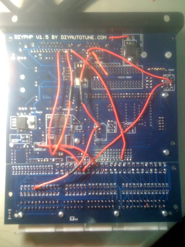
1. 1Q--input 1 in---> input 1 out---> 1J --->external time delay relay ---> AC clutch
2. 1J---input 2 in--->input2 out--->PE1 (table switching)
3. ALED--> AC fan relay <---1J
4. WLED-->external relay interrupting 1Q (to implement TPS cutoff)
Oooh I still have FLEX (PE0) free. So I can keep table switching by using FLEX to trigger status 4
Proposed changes.
1a. 1Q---> input 1 in--> input 1 out--->FLEX --->triggers status 4
1b. WLED (triggered by status 4 and can implement time delay and TPS cutoff)--> 1J ---> AC clutch
2. 1J---input 2 in--->input2 out--->PE1 (table switching)
3. ALED (triggered by status 4)---> AC relay ---> AC fan
Is this correct? Am I using input circuits correctly?
With this (hopefully) final rewiring, I can get rid of the time delay relay and the TPS cutoff relay. I can also get rid of the 1J trigger to the AC relay (and have the AC fan turn on with a different time delay from the AC clutch.)
Last edited by Greg G; 10-10-2011 at 07:38 AM.
Reply
0
0
10-10-2011, 08:35 AM
#410
Try this update... ms2extra_3.1.3_idleup_v2
I'll be keen to hear what you think of the battery idle correction (too raw, not enough etc)
An example of the duty add.. for when the factor is 1 (high values multiply that up)
14.0 -8
13.8 -6
13.5 -3
13.2 0
13.0 2
12.0 12
11.5 17
11.0 22
10.0 32
9.0 42
G
I'll be keen to hear what you think of the battery idle correction (too raw, not enough etc)
An example of the duty add.. for when the factor is 1 (high values multiply that up)
14.0 -8
13.8 -6
13.5 -3
13.2 0
13.0 2
12.0 12
11.5 17
11.0 22
10.0 32
9.0 42
G
Last edited by gslender; 10-10-2011 at 08:56 AM. Reason: add table example
Reply
0
0

 10-11-2011, 01:36 AM
#413
Newb

Join Date: May 2011
Posts: 30
Total Cats: 0
Proposed changes.
1a. 1Q---> input 1 in--> input 1 out--->FLEX --->triggers status 4
1b. WLED (triggered by status 4 and can implement time delay and TPS cutoff)--> 1J ---> AC clutch
2. 1J---input 2 in--->input2 out--->PE1 (table switching)
3. ALED (triggered by status 4)---> AC relay ---> AC fan
Is this correct? Am I using input circuits correctly?
1Q ---> PEO
WLED ---> IN on Input 1
OUT on Input 1 ---> 1J
Reply
0
0
10-11-2011, 02:03 AM
#414
Junior Member
Thread Starter
Join Date: Jun 2007
Posts: 411
Total Cats: 0
I had flyback issues with 1J--> PE1 a few months ago, so I had to make it
1J--->input2 in---> input2 out---> PE1. Which, in retrospect wasn't really the issue (something was wrong with the harness).
Which leaves me as confused as ever
I was also under the impression that wled ---> 1J should be ok...
Someone set me straight please!
1J--->input2 in---> input2 out---> PE1. Which, in retrospect wasn't really the issue (something was wrong with the harness).
Which leaves me as confused as ever
I was also under the impression that wled ---> 1J should be ok...
Someone set me straight please!
Reply
0
0
10-11-2011, 11:29 AM
#415
Newb
Join Date: May 2011
Posts: 30
Total Cats: 0
Makes sense. But i'm only one week in on the msq train So i'll defer to people with more expertise. How i described it is how i have it right now, and i must say, this new firmware and the added AC idle control is allowing my car to idle at last...
Reply
0
0
10-12-2011, 02:30 AM
#416
Junior Member
Thread Starter
Join Date: Jun 2007
Posts: 411
Total Cats: 0
Tried the latest version of the idle up 'gslender' code with the idle valve voltage correction, and it is a significant improvement! The voltage correction actually adds to the AC idle up, so you can actually decrease the AC idle up value. Aside from that, it handles the RPM droops from fan & headlight loads much better than the closed loop PID code. Why? Because the PID code, no matter how well tuned, is reactive. It will always be late. The idle up code and voltage correction are immediate responses (and with the correct wiring, the AC idle up becomes a feedforward action).
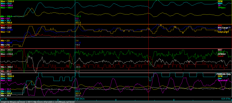
Posted are the logs with voltage correction factors at 0,1,2,3,4. At 3, the RPMs *rise* when there is a voltage drop. At 4, the idle valve duty causes oscillations in steady state idle already. My sweet spot is somewhere between 1 and 2.
An explanation of the logs: the first voltage droop is the AC engaging. The second is the main fan, which I set up to turn on 3 seconds after the AC engages, so we get consistent graphs. The vertical line/markers indicate the headlights being turned on & off. Pay attention to how the PWM Idle Duty responds to voltage droops, and how it affects the RPMs, and how the battery correction factor changes it.
Posted are the logs with voltage correction factors at 0,1,2,3,4. At 3, the RPMs *rise* when there is a voltage drop. At 4, the idle valve duty causes oscillations in steady state idle already. My sweet spot is somewhere between 1 and 2.
An explanation of the logs: the first voltage droop is the AC engaging. The second is the main fan, which I set up to turn on 3 seconds after the AC engages, so we get consistent graphs.
The vertical line/markers indicate the headlights being turned on & off. Pay attention to how the PWM Idle Duty responds to voltage droops, and how it affects the RPMs, and how the battery correction factor changes it.
Reply
0
0
10-12-2011, 02:54 AM
#417
Posted are the logs with voltage correction factors at 0,1,2,3,4. At 3, the RPMs *rise* when there is a voltage drop. At 4, the idle valve duty causes oscillations in steady state idle already. My sweet spot is somewhere between 1 and 2.
An explanation of the logs: the first voltage droop is the AC engaging. The second is the main fan, which I set up to turn on 3 seconds after the AC engages, so we get consistent graphs. The vertical line/markers indicate the headlights being turned on & off. Pay attention to how the PWM Idle Duty responds to voltage droops, and how it affects the RPMs, and how the battery correction factor changes it.
An explanation of the logs: the first voltage droop is the AC engaging. The second is the main fan, which I set up to turn on 3 seconds after the AC engages, so we get consistent graphs.
The vertical line/markers indicate the headlights being turned on & off. Pay attention to how the PWM Idle Duty responds to voltage droops, and how it affects the RPMs, and how the battery correction factor changes it.Unfortunately you'll probably have to start again with your values/tuning for idle, but it will make the whole process produce a better result.
Probably won't bubble out a new firmware for the next 6 hours... so depending on your time zone, this might be tomorrow.

G
Reply
0
0
10-13-2011, 03:59 AM
#418
Junior Member
Thread Starter
Join Date: Jun 2007
Posts: 411
Total Cats: 0
Installed and tested version 3 today. Didn't have much time to fine tune, but basically the RPM target adder works! I have to redo my table binning for spark/fuel to accommodate the 2 targets...
For this I reduced the PID action even further by changing min/max RPM from 900/1800 to 900/2000. Also reduced AC idle up from 13.5 to 12.1, and changed vcorr factor to 12 (the code changed, this is similar to 1.2 in the previous version). RPM target is 950, with an adder value of 50 on AC engagement, to make a target of 1000RPM.
I believe the small oscillations are from the spark advance. I need to dial down the slope to make a wider "valley" to accomodate the RPM targets. And note the scale of the RPM-- those oscillations are hardly felt. Will try lowering the base idle to 900 with an adder of 100, it looks very doable.
Reply
0
0
10-14-2011, 02:47 AM
#419
Junior Member
Thread Starter
Join Date: Jun 2007
Posts: 411
Total Cats: 0
Noticed this while reviewing the logs... if the voltage drop/electrical load occurs during deceleration while in open loop and the software dashpot is engaged, the calculated dashpot value ends up too low and a ~200 rpm droop occurs. Not a huge issue, but if the idle valve voltage correction could be applied to the dashpot value, it would get rid of this issue. It is relevant because if you apply a TPS cutoff to the AC compressor, there will probably be a greater chance that it will re-engage during the deceleration/dashpot event.
Reply
0
0


