
Golferluke attempts to build an ms3...

Thread Starter
Junior Member
Joined: Oct 2009
Posts: 496
Total Cats: 3
From: Springfield, MO
Got my ms3 in the mail the other day 
I figured I might as well make a build thread because I'm gonna have all sorts of questions I couldn't find searching. I bought a ms2 last week, found out it didn't have the right ms2 board, and the same day ms3s came back in stock at diy so I bought a kit. Only problem is I don't know jack about circuits and i've never soldered before. No problem right? Well after some advice I got all of the soldering stuff I needed and last night I spent a few hours practicing soldering (an old router selflessly gave its life for the cause)
Today I started on the board, I'm not going as fast as some but I've got all weekend and I havn't hit any snags yet (well, not from soldering skills anyways) but now I'm at step 50 and I don't know what to do. So far I've been following this and this but I'm stuck on the inputs. Should I follow the msextra 99-00 instructions msextra 99-00 instructions or keep following franks instructions? Franks are easier to understand but he also did some things different than me (pwm board and seq inj board) and I don't know how they'll affect my build. What should I do? Now that I think about it, they might be the same thing, I just can't read circuit maps.
Unless I here back from you guys pretty soon I'm probabbly just going to skip it for now and move on to 53.
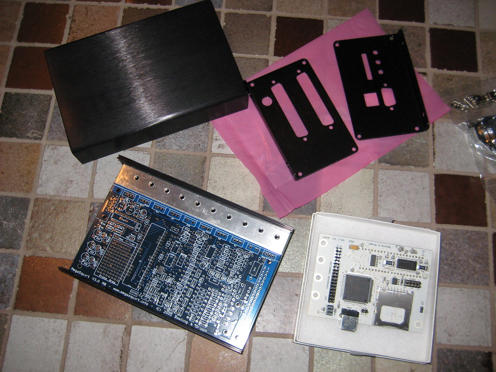
Pictars
Yay new parts!
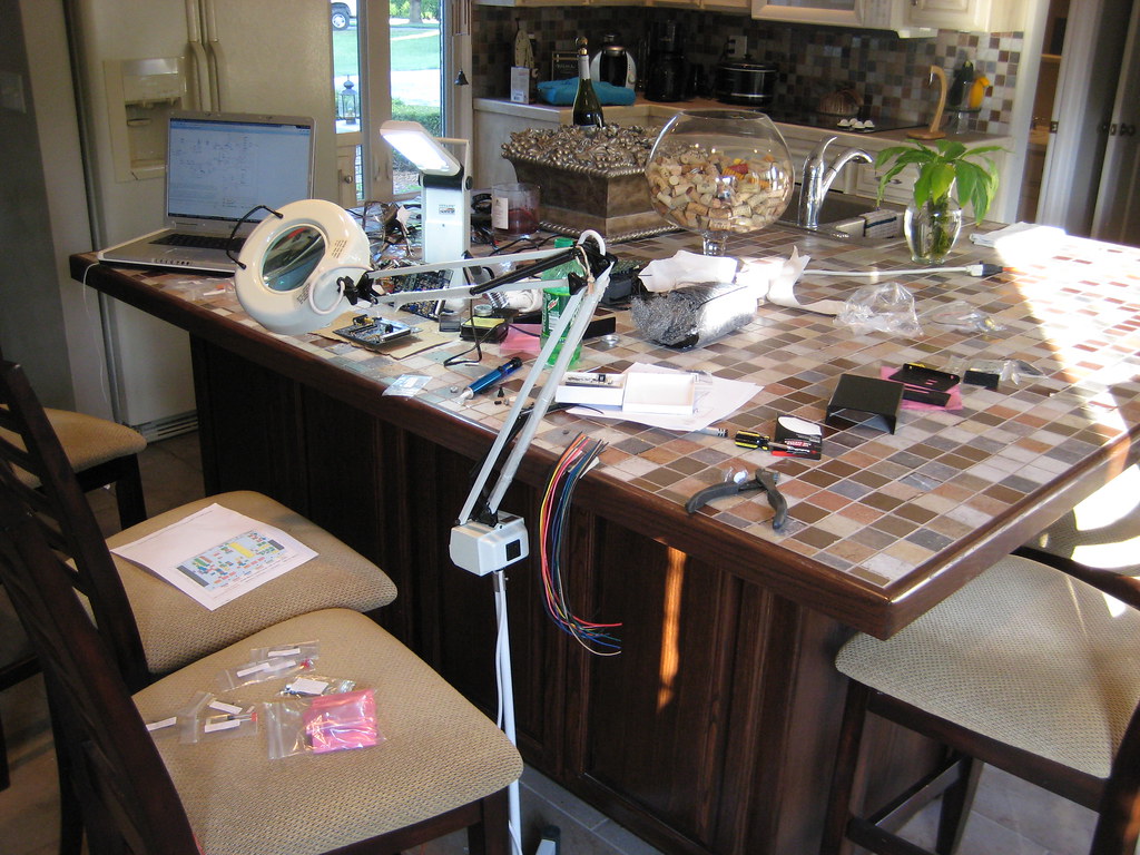
Work space: 7x7 islands come in handy for projects (and beer pong)
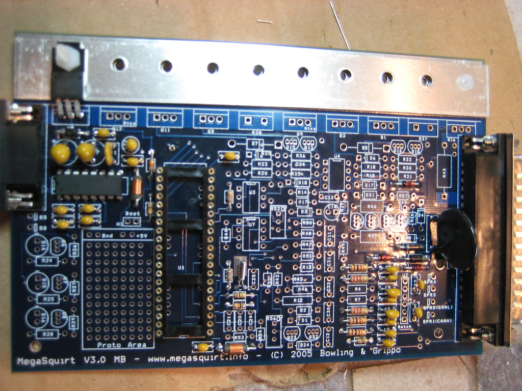
Progress so far.
I figured I might as well make a build thread because I'm gonna have all sorts of questions I couldn't find searching. I bought a ms2 last week, found out it didn't have the right ms2 board, and the same day ms3s came back in stock at diy so I bought a kit.
Only problem is I don't know jack about circuits and i've never soldered before. No problem right? Well after some advice I got all of the soldering stuff I needed and last night I spent a few hours practicing soldering (an old router selflessly gave its life for the cause) Today I started on the board, I'm not going as fast as some but I've got all weekend and I havn't hit any snags yet (well, not from soldering skills anyways) but now I'm at step 50 and I don't know what to do. So far I've been following this and this but I'm stuck on the inputs. Should I follow the msextra 99-00 instructions msextra 99-00 instructions or keep following franks instructions? Franks are easier to understand but he also did some things different than me (pwm board and seq inj board) and I don't know how they'll affect my build. What should I do? Now that I think about it, they might be the same thing, I just can't read circuit maps.
Unless I here back from you guys pretty soon I'm probabbly just going to skip it for now and move on to 53.
Pictars
Yay new parts!
Work space: 7x7 islands come in handy for projects (and beer pong)
Progress so far.
Last edited by Golferluke; Aug 8, 2010 at 06:07 PM.
Reply
 0
0

0


where's r4 and r7?
welcome to the club:

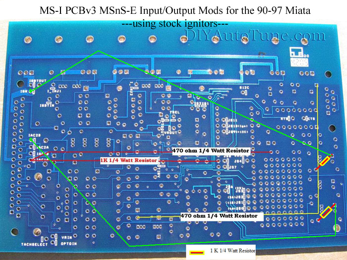
If you follow my diagram you'll have all components installed that you need, then you just need to mod the board for input/outputs/alternator. You'll need to follow his directions for cam/crank inputs. I have no documentation fora 99-00 build.
welcome to the club:
If you follow my diagram you'll have all components installed that you need, then you just need to mod the board for input/outputs/alternator. You'll need to follow his directions for cam/crank inputs. I have no documentation fora 99-00 build.
Reply
0
0
Thread Starter
Junior Member
Joined: Oct 2009
Posts: 496
Total Cats: 3
From: Springfield, MO
Thanks, ok cool I'll keep going then after i get some grub. I'm not sure about r4 and r7, I wondered the same but havn't seen them in the instructions yet.
EDIT: step 54
oh and I didn't realize how much fun just building it would be, its a blast!
EDIT: step 54
oh and I didn't realize how much fun just building it would be, its a blast!
Reply
0
0
Thread Starter
Junior Member
Joined: Oct 2009
Posts: 496
Total Cats: 3
From: Springfield, MO
Ya I bet! Ok heres todays progress. Its 2:30am so we'll pick it back up in the morning.
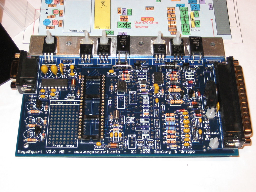
Pretty much done with the main part. Parts i'm missing:
R12:don't have a 470 ohm resistor, need to make a radio shack run.
Q7: had a question on this one, can I use ZTX450(Q4) instead of 2n2222? If not will RS have these?
LEDs: still don't quite understand whats going on down in the southwestern region of the board yet, got some reading to do.
c25: I err uh...i'll get it tomorrow
I'm gonna have to read through the inputs/spark stuff tommorow and put together a shopping list besides 470ohm resistors (what tolerance?) and 2n2222s.
Reply
0
0
a 5-pack of 470 5% for $0.99 will work.
For q7, use the transistor for q4 that you didnt place. But radioshack has 2n2222 in a 20 pack multipack of transistors for like $2.00
looks like you are at the point where you need to mod the board for miata specific install. You can follow either of Frank's diagrams for the spark outputs, I prefer to keep the leds in place. The main thing you need to worry about in the cam/crank input circuit.
Reply
0
0
Thread Starter
Junior Member
Joined: Oct 2009
Posts: 496
Total Cats: 3
From: Springfield, MO
well I just got back from rs, using this as a shopping list I got:
8pin ic
2n2222s
tlo82
1/2 watt, 5% 3.3k
1/4 watt, 5% 470
1/4 watt, 5% 22k
1/2 watt, 5% 4.7k
1/2 watt, 5% 10k
but couldn't find
1nf (don't really know what this is )
)
13k
18k
I'm getting worried about building these circuits, I really want to learn how to do this stuff but I don't even know if im getting the right parts, let alone what the hell do do with them. I've been trying to figure out what all these schematics mean but I don't even know which ones the right one to use. they all just look like hieroglyphics to me.
this one?
this one?
this one?
this one?
8pin ic
2n2222s
tlo82
1/2 watt, 5% 3.3k
1/4 watt, 5% 470
1/4 watt, 5% 22k
1/2 watt, 5% 4.7k
1/2 watt, 5% 10k
but couldn't find
1nf (don't really know what this is
)13k
18k
I'm getting worried about building these circuits, I really want to learn how to do this stuff but I don't even know if im getting the right parts, let alone what the hell do do with them. I've been trying to figure out what all these schematics mean but I don't even know which ones the right one to use. they all just look like hieroglyphics to me.
this one?
this one?
this one?
this one?
Reply
0
0
you gotta stick with ones persons build. if you are following franks, just use franks circuits. you are mixing up a whole bunch of different ways to bring in the sensors.
get components at digi-key.com; 1nf is a capacitor.
get components at digi-key.com; 1nf is a capacitor.
Reply
0
0
Thread Starter
Junior Member
Joined: Oct 2009
Posts: 496
Total Cats: 3
From: Springfield, MO
Which would be easiest? I haven't really picked a build yet, all I've done is build the schematic on msextra. I would really like to get this done and not have to wait a week for parts, is there any way to make a circuit from parts I could pick up at rs?
EDIT, ok i think i'm finally starting to understand the msextra schematic, I should be able to build the ms3extra with rs parts but can i swap the mc34072ap with the tl082?
EDIT, ok i think i'm finally starting to understand the msextra schematic, I should be able to build the ms3extra with rs parts but can i swap the mc34072ap with the tl082?
Last edited by Golferluke; Aug 1, 2010 at 06:37 PM.
Reply
0
0
Thread Starter
Junior Member
Joined: Oct 2009
Posts: 496
Total Cats: 3
From: Springfield, MO
YAY! Progress!
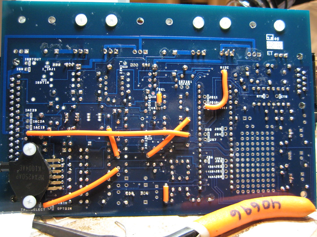
Today I found 18k resistors at radio shack (only place here that still has resistors) and I stacked 12k and a 1k for my 13k resistors. Then I tought my self wtf the schematics mean (or atleast how to follow them) after all this I went to work and got my inputs done Check them out, followed franks instructions but I did have a question though, I had to undo r13 and run a 4.7k from the left side of r13 to the bottom of r49. Since r13 was originally filled, will this through something off? hope not 

Tommorow, figure out how to do the spark.
PS
OMFG R48 was a pain in the ***. Took me like an hour, had to flatten the leads with plyers and line them up perfectly straight.
Today I found 18k resistors at radio shack (only place here that still has resistors) and I stacked 12k and a 1k for my 13k resistors. Then I tought my self wtf the schematics mean (or atleast how to follow them) after all this I went to work and got my inputs done
Check them out, followed franks instructions but I did have a question though, I had to undo r13 and run a 4.7k from the left side of r13 to the bottom of r49. Since r13 was originally filled, will this through something off? hope not Tommorow, figure out how to do the spark.
PS
OMFG R48 was a pain in the ***. Took me like an hour, had to flatten the leads with plyers and line them up perfectly straight.
Reply
0
0


Reply
0
0

Thread Starter
Junior Member
Joined: Oct 2009
Posts: 496
Total Cats: 3
From: Springfield, MO
ok quick question, besides jumpering d14 and d16 and putting 1k res in 26 and 29, the rest is normal right?

Also, I'd like to keep the leds like on this one but I don't really understand what to do with the 330 resistors.

EDIT: wait, r29 and r26 are already 1k, what am I supposed to do differently besides jumper d14 and d16?
Also, I'd like to keep the leds like on this one but I don't really understand what to do with the 330 resistors.
EDIT: wait, r29 and r26 are already 1k, what am I supposed to do differently besides jumper d14 and d16?
Last edited by Golferluke; Aug 3, 2010 at 09:41 PM.
Reply
0
0

I confess I don't understand why you have resistors in transistor locations, coming directly off CPU legs and going from one locationto another.
I don't remember any of that being documented anywhere, is it a new easier way of building the boards up?
EDIT: sorry didn't notice your comment on the 1st pass that your following Franks guide!
I don't remember any of that being documented anywhere, is it a new easier way of building the boards up?
EDIT: sorry didn't notice your comment on the 1st pass that your following Franks guide!
Reply
0
0

Senior Member
Joined: Nov 2007
Posts: 999
Total Cats: 73
From: Belgium
I'm getting worried about building these circuits, I really want to learn how to do this stuff but I don't even know if im getting the right parts, let alone what the hell do do with them. I've been trying to figure out what all these schematics mean but I don't even know which ones the right one to use. they all just look like hieroglyphics to me.
this one?
this one?
this one?
this one?
this one?
this one?
this one?
this one?
There's a couple more like that if you decide to build Jean's PWM idle circuit (which you definitely must have).
If you want to keep the leds, just solder 2 extra resistors on the underside of the board like the standard setup. Never mind the 1K and don't use 470R but 330R.
Edit: looking at your pics, you clearly built way too much. For example, the CPU clock circuit is only needed on MS1.
You should really print out (yes print them out) all circuits here. You don't have to know how they work, just understand that each circuit has a seperate function. If you don't need that particular function, than leave out the corresponding circuit.
In my build, I left out the CPU clock, but not the rest of the power circuit of course.
I also didn't need the leds, so I left out these 3 circuits.
Etc etc.
Last edited by WestfieldMX5; Aug 4, 2010 at 07:05 AM.
Reply
0
0
Thread Starter
Junior Member
Joined: Oct 2009
Posts: 496
Total Cats: 3
From: Springfield, MO
Thanks for the info, I'll post a couple updated pics later tonight. I ended up leaving out the leds but i'm lost as to what wires to jumper. You posted a picture of the ms1 build, was that just to show me how to do the leds or do that wiring transfer over to this as well?
For the main build I followed the miata schematic then used your input circuits, I didn't know what i needed by following your build because of the seperate boards. So do I need to remove stuff or can I just leave it? Oh and the links you posted are just coming up as the msextra logo for some reason.
For the main build I followed the miata schematic then used your input circuits, I didn't know what i needed by following your build because of the seperate boards. So do I need to remove stuff or can I just leave it? Oh and the links you posted are just coming up as the msextra logo for some reason.
Reply
0
0
Senior Member
Joined: Nov 2007
Posts: 999
Total Cats: 73
From: Belgium
That's just to show you how to do the resistors for the spark outputs. IOW, solder them to the underside of the board. The principle is the same. The wiring obviously not.
Print out the schematics in the link I gave you. You really need to look into them to get some basic understanding of how things work.
If you're following my writeup, print it out as well and read it through with the original schematics next to it. Try to understand each step and what I modified.
The reason I didn't install the leds is because I can't see them anyway under the dash, so why bother? The oem ecu has no leds either (like most aftermarket ecu's). It makes the build less complicated as the 330 resistors are already there. To build the spark output, just jumper the led and that jumper becomes your spark output. How easy can it be?
If you want to see flashing leds, add the resistors on the underside of the pcb.
Same thing with the tacho, I have no use for the D15 led, so I used that area of the pcb as tacho output instead.
Alternatively, you could build the fan output in that spot and keep the led as an indicator when the fan turns on. Build the tacho output in the proto area if you do.
Because some of my circuits are built in areas of the board that normally serve other functions (like the injector circuit and the pwm converter circuit), obviously those areas need to be entirely empty before you start building something else in them.
For instance, I built the low alternator warning circuit and the pwm converter circuit in the area of the pcb which used to be the injector output. My injector output is on Jean's seperate board. I don't think I used the clock circuit area for anything else so you don't need to remove the components, but they might come in handy for other things. The general miata schematic is MS1, not MS2/3, that's why it has the cpu clock circuit. Only MS1 needs it.
Someone should make a similar basic writeup for a standard 99-00 MS2 without Jean's boards. I might be tempted to if there's intrest. OTOH, full sequential fuel is nice to have and the pwm converter is needed anyway, so why not add them?
I haven't looked into MS3 yet, maybe it has outputs for full sequential already?
Last edited by WestfieldMX5; Aug 4, 2010 at 01:25 PM.
Reply
0
0
Thread Starter
Junior Member
Joined: Oct 2009
Posts: 496
Total Cats: 3
From: Springfield, MO
That's just to show you how to do the resistors for the spark outputs. IOW, solder them to the underside of the board. The principle is the same. The wiring obviously not.
Print out the schematics in the link I gave you. You really need to look into them to get some basic understanding of how things work.
If you're following my writeup, print it out as well and read it through with the original schematics next to it. Try to understand each step and what I modified.
The reason I didn't install the leds is because I can't see them anyway under the dash, so why bother? The oem ecu has no leds either (like most aftermarket ecu's). It makes the build less complicated as the 330 resistors are already there. To build the spark output, just jumper the led and that jumper becomes your spark output. How easy can it be?
If you want to see flashing leds, add the resistors on the underside of the pcb.
Same thing with the tacho, I have no use for the D15 led, so I used that area of the pcb as tacho output instead.
Alternatively, you could build the fan output in that spot and keep the led as an indicator when the fan turns on. Build the tacho output in the proto area if you do.
Because some of my circuits are built in areas of the board that normally serve other functions (like the injector circuit and the pwm converter circuit), obviously those areas need to be entirely empty before you start building something else in them.
For instance, I built the low alternator warning circuit and the pwm converter circuit in the area of the pcb which used to be the injector output. My injector output is on Jean's seperate board. I don't think I used the clock circuit area for anything else so you don't need to remove the components, but they might come in handy for other things. The general miata schematic is MS1, not MS2/3, that's why it has the cpu clock circuit. Only MS1 needs it.
Someone should make a similar basic writeup for a standard 99-00 MS2 without Jean's boards. I might be tempted to if there's intrest. OTOH, full sequential fuel is nice to have and the pwm converter is needed anyway, so why not add them?
I haven't looked into MS3 yet, maybe it has outputs for full sequential already?
Print out the schematics in the link I gave you. You really need to look into them to get some basic understanding of how things work.
If you're following my writeup, print it out as well and read it through with the original schematics next to it. Try to understand each step and what I modified.
The reason I didn't install the leds is because I can't see them anyway under the dash, so why bother? The oem ecu has no leds either (like most aftermarket ecu's). It makes the build less complicated as the 330 resistors are already there. To build the spark output, just jumper the led and that jumper becomes your spark output. How easy can it be?
If you want to see flashing leds, add the resistors on the underside of the pcb.
Same thing with the tacho, I have no use for the D15 led, so I used that area of the pcb as tacho output instead.
Alternatively, you could build the fan output in that spot and keep the led as an indicator when the fan turns on. Build the tacho output in the proto area if you do.
Because some of my circuits are built in areas of the board that normally serve other functions (like the injector circuit and the pwm converter circuit), obviously those areas need to be entirely empty before you start building something else in them.
For instance, I built the low alternator warning circuit and the pwm converter circuit in the area of the pcb which used to be the injector output. My injector output is on Jean's seperate board. I don't think I used the clock circuit area for anything else so you don't need to remove the components, but they might come in handy for other things. The general miata schematic is MS1, not MS2/3, that's why it has the cpu clock circuit. Only MS1 needs it.
Someone should make a similar basic writeup for a standard 99-00 MS2 without Jean's boards. I might be tempted to if there's intrest. OTOH, full sequential fuel is nice to have and the pwm converter is needed anyway, so why not add them?
I haven't looked into MS3 yet, maybe it has outputs for full sequential already?
Obviously I don't have the knowledge to do a writeup but i'd be happy to supply pictures of a normal board done with your mods (after cleaning up the un-needed bits) if you wanted to do a writeup or add to yours.
Reply
0
0


