
Golferluke attempts to build an ms3...


Senior Member
Joined: Nov 2007
Posts: 999
Total Cats: 73
From: Belgium
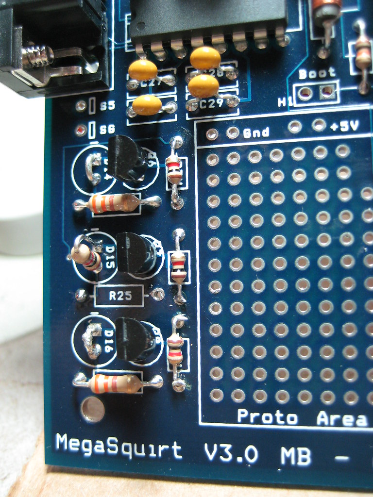
I can't see where you took it from, but assuming the long wire going to the tacho output is indeed 12V, everything is looking good. The D14/16 jumpers are your spark outputs. The resistor in D15 is the tacho output.
You forgot the jumper from VrOutInv to JS10.
You forgot the jumper from VrOutInv to JS10.
Reply
 0
0

0
Thread Starter
Junior Member
Joined: Oct 2009
Posts: 496
Total Cats: 3
From: Springfield, MO
Oops, thanks, I'll get that today. So now I need to figure out what I'm going to do about the alternator, I don't have another .001 cap, I think they have them at radioshack but they are 500v not 50v. Also they don't have any 1% resistors. Is there anyway to do it with other parts? I have plenty of .01 caps and 47k/51k 5% resistors. I can't hardly even find the right capacitor online.
Option B is just find a NA alt.
Option B is just find a NA alt.
Reply
0
0
Senior Member
Joined: Nov 2007
Posts: 999
Total Cats: 73
From: Belgium
You need to use the correct caps. Voltage doesn't matter as long as it's at least 16V.
You could try 5% resistors, but then your output voltage will be off. Measure the values of the resistors you have and calculate the output voltage (formula on my site I believe). If the results is 14.x volts, you're good.
You could try 5% resistors, but then your output voltage will be off. Measure the values of the resistors you have and calculate the output voltage (formula on my site I believe). If the results is 14.x volts, you're good.
Reply
0
0

Oops, thanks, I'll get that today. So now I need to figure out what I'm going to do about the alternator, I don't have another .001 cap, I think they have them at radioshack but they are 500v not 50v. Also they don't have any 1% resistors. Is there anyway to do it with other parts? I have plenty of .01 caps and 47k/51k 5% resistors. I can't hardly even find the right capacitor online.
Option B is just find a NA alt.
Option B is just find a NA alt.
Dimitris
Reply
0
0
Thread Starter
Junior Member
Joined: Oct 2009
Posts: 496
Total Cats: 3
From: Springfield, MO
Ok so after finding out how remarkably little information there is for keeping the a/c on an NB, and having trouble with alt circuit, I'm thinking about making a change. How hard would this be to parallell? As in the ecu only controlling a/c and alternator, standalone for everything else. I already have all the connectors to make a full 'boomslang' just need to grab some pins for male side. I don't even care about fixing ac idle droop, just want it to turn on when I hit the button and my battery not go dead.
ps, got done with vics and fan control pretty much done with everything but ac and alt.
edit: Actually it wouldn't even have to be a full boomslang, just like a regular db37-64pin but with a plugs coming off after the 64pin to plug into stock ecu. I don't even care about fixing ac idle droop, just want it to turn on when I hit the button.
ps, got done with vics and fan control
pretty much done with everything but ac and alt.edit: Actually it wouldn't even have to be a full boomslang, just like a regular db37-64pin but with a plugs coming off after the 64pin to plug into stock ecu. I don't even care about fixing ac idle droop, just want it to turn on when I hit the button.
Last edited by Golferluke; Aug 6, 2010 at 01:29 AM.
Reply
0
0


Thread Starter
Junior Member
Joined: Oct 2009
Posts: 496
Total Cats: 3
From: Springfield, MO
Edited for noobness, this whole post was just full of fail lmao. I think I understand it now, but how do I connect it to js9? Do I bring the cable directly inside the box to js9 or to pin 5 and jump spr3-js9?
I've decided I'll just build this circuit and pick up an alternator locally. Going to build my harness tonight and hopefully be done with ms by tomorrow.
I've decided I'll just build this circuit and pick up an alternator locally. Going to build my harness tonight and hopefully be done with ms by tomorrow.
Last edited by Golferluke; Aug 7, 2010 at 02:10 AM.
Reply
0
0
Thread Starter
Junior Member
Joined: Oct 2009
Posts: 496
Total Cats: 3
From: Springfield, MO
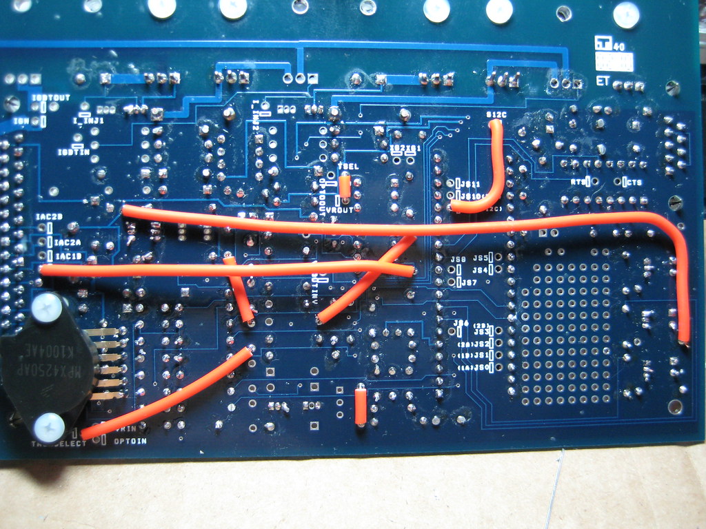
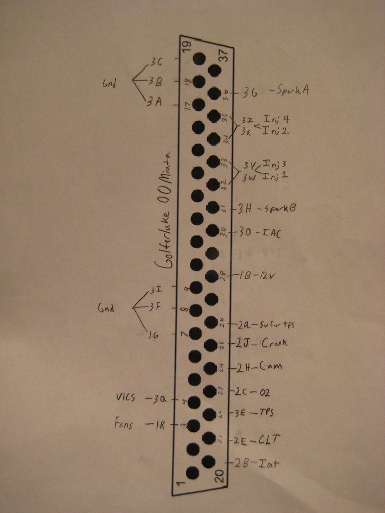
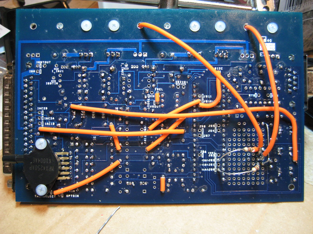
Ok after all night of pouring over miata and 3.0 board schematics I think I've finally got it. Can somebody check this for me? I think everythings right except idk about injectors. Oh and clutch ground but figured it couldn't hurt. Also, heres pictures of Where the boards at as of now. Did I miss anything? (I know no bodys going to go over it bit by bit but if you notice something lmk)
Reply
0
0
Senior Member
Joined: Nov 2007
Posts: 999
Total Cats: 73
From: Belgium
Don't bring it in on JS9, that's your 12V input to activate JS0 and JS2.
Those mile long wires are interesting. You could have soldered short wires directly on the underside.
Resistors are interesting too. I bet they're gonna touch the inside of the case. You should try to put your components on the component side. FWIW.
Those mile long wires are interesting. You could have soldered short wires directly on the underside.
Resistors are interesting too. I bet they're gonna touch the inside of the case. You should try to put your components on the component side. FWIW.
Reply
0
0
Thread Starter
Junior Member
Joined: Oct 2009
Posts: 496
Total Cats: 3
From: Springfield, MO
Sorry for noobness, by relay you mean the 2n2222? So it doesn't go to the board at all?
Mile long wires because I didn't want to run wires under map sensor. I checked for clearance on case and put a piece of rubber between the close wires. I built the circuits on the bottom so I could have more room for the alt circuit I was going to build on the top.
What do you guys think about the db37 layout?
Last edited by Golferluke; Aug 7, 2010 at 01:16 PM.
Reply
0
0
Thread Starter
Junior Member
Joined: Oct 2009
Posts: 496
Total Cats: 3
From: Springfield, MO
Edit: nvm got firmware loaded and tunerstudio working.
Is there a basemap for 99-00 miatas somewhere? Is it ok to use the diypnp map from diyautotune?
Frank would you mind taking a look at my db37 layout?
Is there a basemap for 99-00 miatas somewhere? Is it ok to use the diypnp map from diyautotune?
Frank would you mind taking a look at my db37 layout?
Last edited by Golferluke; Aug 9, 2010 at 01:58 AM.
Reply
0
0
Thread Starter
Junior Member
Joined: Oct 2009
Posts: 496
Total Cats: 3
From: Springfield, MO
Cool thanks, is there anyway to check to see if my board is wired correctly besides a stim or do I need to just start her up and look for things that went wrong? I disconnected spark a and b for loading the firmware (read somewhere its possible to fry coils?) but I plan on puttin them back on tonight. Should I just load base map, turn the key and see what happens? Doesn't sound like the safest option but I don't know what else to do lol.
Reply
0
0
Senior Member
Joined: Nov 2007
Posts: 999
Total Cats: 73
From: Belgium
layout of the db37 is fine except you forgot a couple:
- fuel pump on pin 37
- tacho output and alternator output. You can put these on iac1b and iac2a (if you'll be building these circuits inside the case that is).
You have spr3 and spr4 left for other things in the future (like, EBC, table switching or launch control).
Actually 7 through 19 and 1&2 are grounds, but you have enough pins covered.
I see that fans & Vics on spr1 and 2 are the mile long wires, those are correct.
Tach inputs on 24 and 25 seem to be ok as well.
Spark outputs on 31 and 36 ok ... I think. I always mix them up and on each build I did, I've had to swap them around. So most likely spark A is on 31 and spark B on 36. You'll notice immediately because the spark will be 180� off and the engine will try to fire on BDC instead of TDC. Should the car not fire, a quick way of checking if swapped sparks are the cause, is by swapping the 2 connectors on the coils.
Don't forget to add the wires from D14 and D16 to the db37.
12V and 5V are ok as well.
You're almost good to fire it up!
- fuel pump on pin 37
- tacho output and alternator output. You can put these on iac1b and iac2a (if you'll be building these circuits inside the case that is).
You have spr3 and spr4 left for other things in the future (like, EBC, table switching or launch control).
Actually 7 through 19 and 1&2 are grounds, but you have enough pins covered.
I see that fans & Vics on spr1 and 2 are the mile long wires
, those are correct.Tach inputs on 24 and 25 seem to be ok as well.
Spark outputs on 31 and 36 ok ... I think. I always mix them up and on each build I did, I've had to swap them around. So most likely spark A is on 31 and spark B on 36. You'll notice immediately because the spark will be 180� off and the engine will try to fire on BDC instead of TDC. Should the car not fire, a quick way of checking if swapped sparks are the cause, is by swapping the 2 connectors on the coils.
Don't forget to add the wires from D14 and D16 to the db37.
12V and 5V are ok as well.
You're almost good to fire it up!
Last edited by WestfieldMX5; Aug 9, 2010 at 03:07 PM.
Reply
0
0
Thread Starter
Junior Member
Joined: Oct 2009
Posts: 496
Total Cats: 3
From: Springfield, MO
Oh I thought nbs had the fuelpump controlled out side the ecu or something. K I'll look the harness wire up and add it. I don't know how to make the tach out citrcuit, I'll check that out when I get home. On the d14 and d16, do I just run a cable from one side of the jumper to whatever Pin 31 and 36 are on the board? (don't remember off the top of my head). I'm picking up an na alternator today I think so no circuit for that.
Reply
0
0


