Two Questions after DIYPNP assembly.
 12-16-2015, 10:57 AM
#1
Newb
Thread Starter

Join Date: Nov 2015
Posts: 9
Total Cats: 0
First post but not without plenty of googlizing and what not.
Car: 1990 NA 1.6 5spd USDM bone stock.
I have an assembled DIYPNP (I assembled it); wideband; EBC solenoid; GM IAT all from DIYautotune.
I followed these pinout instructions on Diyautotune's site:
1990-93
For the most part, the above will mirror my final setup (minus the coils but those are listed as *stock config* so I jumpered that way; and the injectors, of which, I'm running rx8 420cc yellows, so just a Reqfuel change in TS)
My questions:
Can I/Should I wire my Innovate MTX-L 3844 as I would with the factory ECU? Specifically, can I wire the yellow wideband wire straight into my existing factory o2 input wire or do I need to create a separate wideband jumper through db15 and on to my board?
For EBC; am I correct in understanding that all I need to do is jumper from PT6 to IN next to r7 and then from OUT to whichever pin on DB15 and then on to my solenoid?
I would love to get this jumpered and in the car before the turbo gear gets here so I can learn the ropes on an NA engine. If I wanted to leave the AFM in place until boost gets here, am I able to run and tune effectively using the MAP WITHOUT installing the GM IAT? As I mentioned previously, I jumpered everything identically to the 1990-93 writeup on DIY's page which calls for an installed GM IAT. If I have to rejumper or remove resistors etc.... then I'll figure something out along the lines of getting a piece of intake pipe to replace the AFM so that I can install the IAT.
Lastly; since the DIY example car has different coils (I am on stock coils) should I stick with the dwell times/type used etc?
Thanks

Reply
 0
0

0
12-16-2015, 12:06 PM
#2
Boost Czar


iTrader: (62)
Join Date: May 2005
Location: Chantilly, VA
Posts: 79,493
Total Cats: 4,080
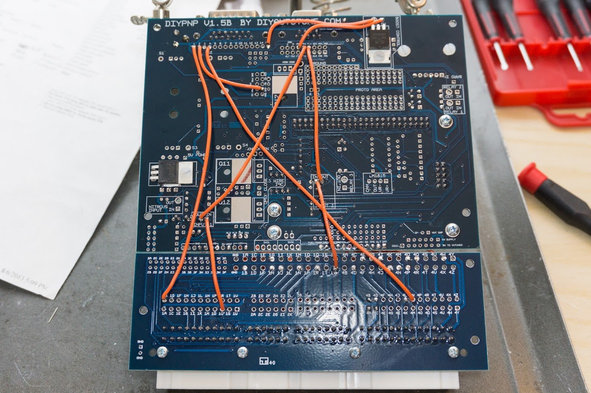
there's a few tiny things id do differently than their build docs:
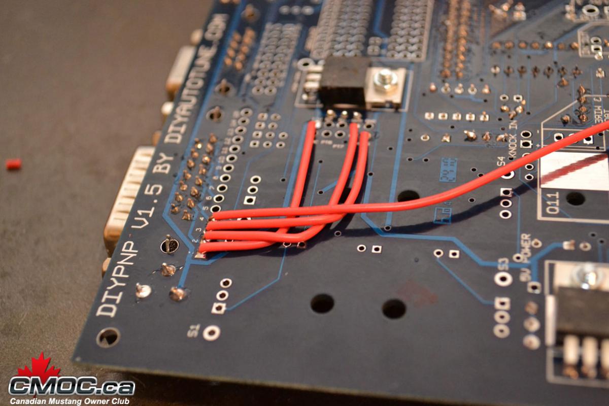
the wire on pin 4 runs to O2.
- I would install R14 and then send 1Q to "input 1 IN", then "input 1 out" to PE1
- Then I'd run WLD to 1J. In software I'd make sure to use a/c idle-up using these seetings.
- I'd rock 1V to Input 2 IN, then Input 2 OUT to flex -- launch control
- for EBC I'd run Pa0 to Boost IN, then Boost OUT to one of the (15) pins on the db15 connector.
- For WBo2 IN, you can use the sotck wire, or send it in throught the same kinda like this:
the wire on pin 4 runs to O2.
Last edited by Braineack; 12-16-2015 at 12:41 PM.
Reply
0
0
12-16-2015, 01:02 PM
#3
Newb
Thread Starter
Join Date: Nov 2015
Posts: 9
Total Cats: 0
there's a few tiny things id do differently than their build docs:
the wire on pin 4 runs to O2.
- I would install R14 and then send 1Q to "input 1 IN", then "input 1 out" to PE1
- Then I'd run WLD to 1J. In software I'd make sure to use a/c idle-up using these seetings.
- I'd rock 1V to Input 2 IN, then Input 2 OUT to flex -- launch control
- for EBC I'd run Pa0 to Boost IN, then Boost OUT to one of the (15) pins on the db15 connector.
- For WBo2 IN, you can use the sotck wire, or send it in throught the same kinda like this:
the wire on pin 4 runs to O2.
Thanks for the response. I'm tracking. One thing I forgot to mention, I'm not going to have A/C so the 1Q>1J thing I omitted. With that being said, I'd like to be wired up in order to have the A/C fan run at the same time as the RAD fan if I can, without having to hack up the fan harness. I'm sure there's a way to do this with MS; I'll snoop around and find the answer. Unless you or someone else wants to be charitable

Any particular reason you'd use PA0 for boost?
And with the w02, am I correct in assuming you did it this way so that you could have ECU provided power and ground for your sensor/gauge?
Again thanks for the reply, I actually utilized your build writeup alongside DIY's when assembling.
Reply
0
0
12-16-2015, 01:07 PM
#4
Boost Czar
iTrader: (62)
Join Date: May 2005
Location: Chantilly, VA
Posts: 79,493
Total Cats: 4,080
do WLD to 1Q.
that will activate the a/c relay -- which will turn on the a/c fan, a/c compressor, and main cooling fan.
yeah, the ground is fine, but you dont want to take 12v that way. You could run a wire directly from 1B on the connector board to the Db15 pin, otherwise it's too much power draw on the circuit within the MS to wire from. Directly from the ECU harness is fine.
Reply
0
0
12-16-2015, 08:31 PM
#5
Boost Czar
iTrader: (62)
Join Date: May 2005
Location: Chantilly, VA
Posts: 79,493
Total Cats: 4,080
oh yeah i also dont use the high side driver circuit for the fuel pump.
I simply run FP (fuel Pump) out to 4O on teh DIYPNP.
This sends it to the AFM connector, where I jump that pin to the normal fuel pump relay pin that the AFM activates mechincally.
I simply run FP (fuel Pump) out to 4O on teh DIYPNP.
This sends it to the AFM connector, where I jump that pin to the normal fuel pump relay pin that the AFM activates mechincally.
Last edited by Braineack; 12-17-2015 at 09:16 AM.
Reply
0
0
01-09-2016, 05:07 AM
#6
Newb
Thread Starter
Join Date: Nov 2015
Posts: 9
Total Cats: 0
So I've hooked everything up accordingly. PA0 to In and Out to Pin 1 on DB15; WLD to 1Q; ALD to 1R; and 1V to Input 2 and Input 1 to FLX.
I've loaded firmware 3.4.0 and started with the base tune available (I believe it's 3.3.a) Got the errors and corrected everything as best as I could using STIM power.
My question is: Whenever I go to programmable on/off or I/O the only input/output I see available is the ALED. I cannot select FLX; WLED or PA0. I'm able to set parameters for ALED (Coolant > 190). Am I not able to select the others because I'm not connected to the vehicle or because those circuits are not functioning and I need to troubleshoot?
Reply
0
0
01-09-2016, 12:09 PM
#7
Boost Czar
iTrader: (62)
Join Date: May 2005
Location: Chantilly, VA
Posts: 79,493
Total Cats: 4,080
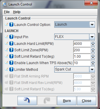
Flex is available under the launch control settings:
Setup fan like this:
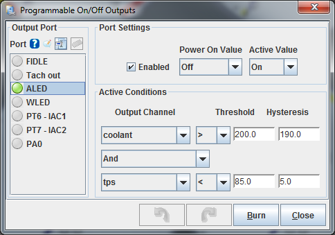
turn it on at 200�F like OEM and then off at 190� turning on at 190�F is premature.
Now where I think you went wrong and didnt follow my instructions:
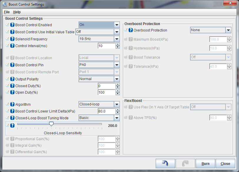
PA0 will be used for boost control.
So PA0 OUT needs to go to BOOST IN. That brings the signal form the MS into the PWM FET Driver.
then BOOST OUT, then goes to the DB15 connector. This sends the signal from PWM FET Driver out to the DB15 connector and then ultimately your boost solenoid.
you probably did this correct, but it's not clear from your post. IN and OUT of what?
1Q is an input. You have it tired to an output. This wont work. ever.
I wrote:
1J is the output. This is the wire the MS will ground to turn on the a/c compressor.
look at the settings below:
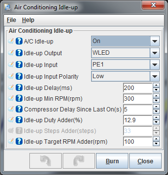
1Q goes to PE1 (through INPUT 1 Circuit) -- the idle up input.
WLED connects to 1J -- the a/c compressor output.
you must move you boost and a/c input/output wires around or itll never work as you have connected.
Setup fan like this:
turn it on at 200�F like OEM and then off at 190� turning on at 190�F is premature.
Now where I think you went wrong and didnt follow my instructions:
PA0 to In and Out to Pin 1 on DB15
So PA0 OUT needs to go to BOOST IN. That brings the signal form the MS into the PWM FET Driver.
then BOOST OUT, then goes to the DB15 connector. This sends the signal from PWM FET Driver out to the DB15 connector and then ultimately your boost solenoid.
you probably did this correct, but it's not clear from your post. IN and OUT of what?
WLD to 1Q
I wrote:
- I would install R14 and then send 1Q to "input 1 IN", then "input 1 out" to PE1
- Then I'd run WLD to 1J. In software I'd make sure to use a/c idle-up using these settings.
1J is the output. This is the wire the MS will ground to turn on the a/c compressor.
look at the settings below:
1Q goes to PE1 (through INPUT 1 Circuit) -- the idle up input.
WLED connects to 1J -- the a/c compressor output.
you must move you boost and a/c input/output wires around or itll never work as you have connected.
Last edited by Braineack; 01-11-2016 at 08:38 AM.
Reply
0
0

 01-11-2016, 02:36 AM
#10
Newb
Thread Starter
Join Date: Nov 2015
Posts: 9
Total Cats: 0
Ok I'll recheck all of my connections when I get home. Looking at your photo above, I'm almost certain I hooked everything up correctly EXCEPT for the A/C where I just went straight to 1Q. I think I interpreted what you had posted in December, to mean WLED->1Q since I am not going to have A/C installed. I understand now, that I need to hook up as you instructed, there just won't be a compressor to turn on. As for the idle up settings, am I correct in assuming that I can zero out those rpm numbers so that my idle doesn't jump way up?
Last edited by 90pandomino; 01-11-2016 at 02:47 AM.
Reply
0
0
01-11-2016, 08:41 AM
#11
Boost Czar
iTrader: (62)
Join Date: May 2005
Location: Chantilly, VA
Posts: 79,493
Total Cats: 4,080
If you don't have a/c then don't populate things for a/c. You wouldn't hook anything to 1J or 1Q and simply disable a/c idle-up in software.
Just fwiw:
connecting WLED to 1Q just wont work for anything.
WLED is an output circuit. 1Q connects directly to the a/c switch on your console. When you press the a/c button, it grounds the signal wire.
Someone that wants the MS to run a/c idle up, would attach 1Q to an INPUT circuit (like i suggested) so the MS can see the input getting grounded, then using WLED as the output, The MS can then provide the ground signal out of 1J which will turn on the a/c relay.
Reply
0
0
01-15-2016, 11:40 AM
#12
Newb
Thread Starter
Join Date: Nov 2015
Posts: 9
Total Cats: 0
So I went through and made sure all connections are correct. I removed the A/C connections on the board, since I won't be running A/C. I'm attaching an .MSQ file in hopes that you could gloss over it real quick and offer any particular advice before I plug in and start up. Thanks again for all your help already.
Reply
0
0

Thread
Thread Starter
Forum
Replies
Last Post
crashnscar
Miata parts for sale/trade
10
07-10-2016 11:49 PM
swankyjosh
Miata parts for sale/trade
1
11-14-2015 01:49 PM
Chiburbian
Miata parts for sale/trade
2
10-26-2015 03:09 PM


