
Help with identification


Thread Starter
Newb
Joined: Aug 2014
Posts: 13
Total Cats: -2
I finally
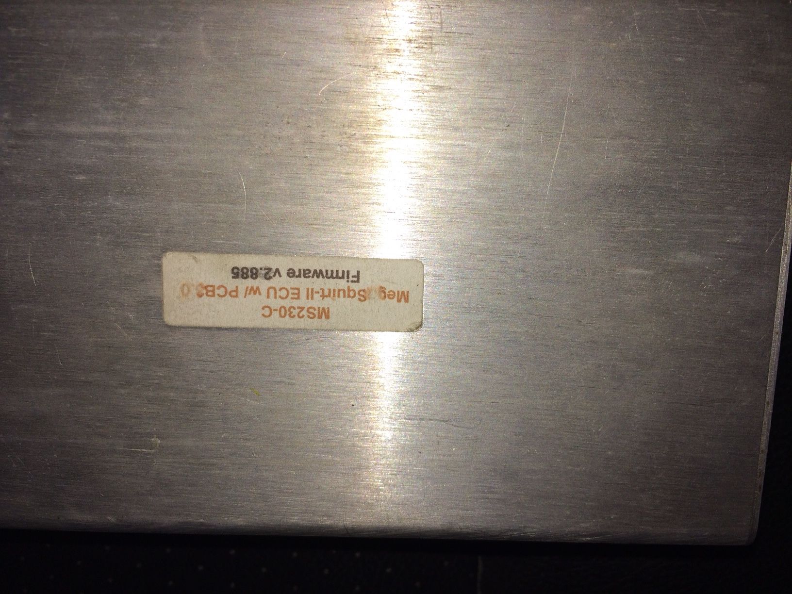
picked up a megasuirt for my turbo build and i have searched all over the net trying to identify the mods that have been done to the board as i need to re attache some of the D37 wires to the ecu adapter because they were crappy solders and came apart.
Can anyone help me out to see how i wire up the fuel pump as i have read 2 different methods and i want to make sure i done fry anything at this point
Car 1990
1.6
Any help would be appreciated
Reply
 0
0

0

Junior Member
Joined: Jan 2016
Posts: 452
Total Cats: 21
I had the same problem a while ago, I had to go through the manual, printed out a diagram of the MS pcb, went through checked every single diode, resistor, capacitor, etc. that the manual said to install. Then I removed all the wires and what not so I knew what I had on the board. Then I installed the mods that I wanted. I wouldn't risk just plugging and playing with a non pnp megasquirt that was used on another car.
manual: MegaSquirt-II - Advanced Electronic Fuel Injection Computer by Bowling & Grippo �2005
diagram of PCB: V3 Main Board
I would however get a wideband asap, also make sure you have a gm iat sensor!
manual: MegaSquirt-II - Advanced Electronic Fuel Injection Computer by Bowling & Grippo �2005
diagram of PCB: V3 Main Board
I would however get a wideband asap, also make sure you have a gm iat sensor!
Reply
0
0
Thread Starter
Newb
Joined: Aug 2014
Posts: 13
Total Cats: -2
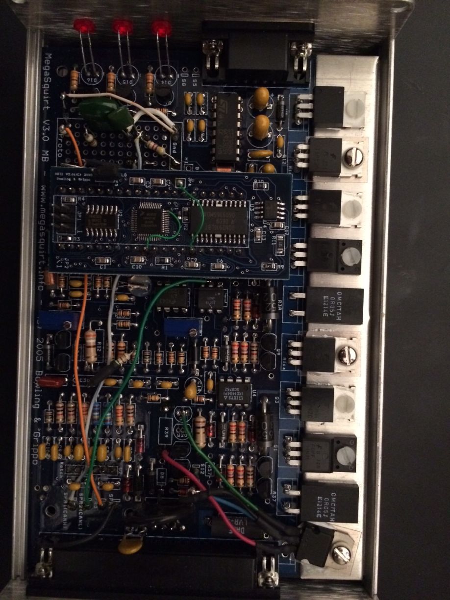
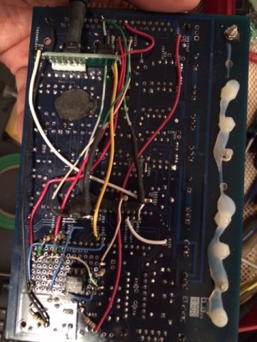
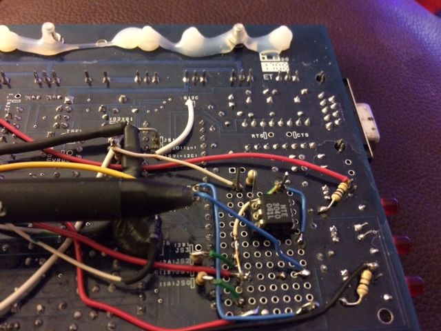
Ok so i ran into a snag as im going over all the wiring.... i noticed in the first pick that Green SPR2 was only connected at one end.. i believe it should be conected to my R1 and then on the back side i noticed the Blue wire on the proto area was only conected at one end and i am at a loss on where its conected to too
Any help is appreciated
Any help is appreciated
Reply
0
0


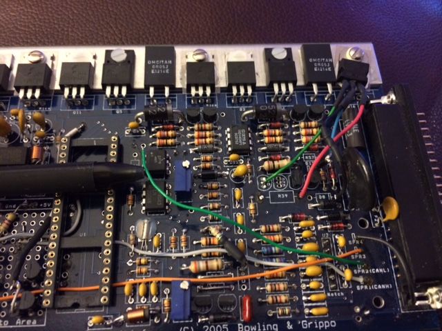
I believe that's a very early MS Labs MS2 if I'm not mistaken, like circa 2008? Actually I think it was just a preassembled unit from DIY and someone did all the modding, but the second opto-isolator for the cam input, and the colored wires, and seq. fuel/spark mods on the cpu, suggests Reverant.
my advice is:Stop moving wires around.
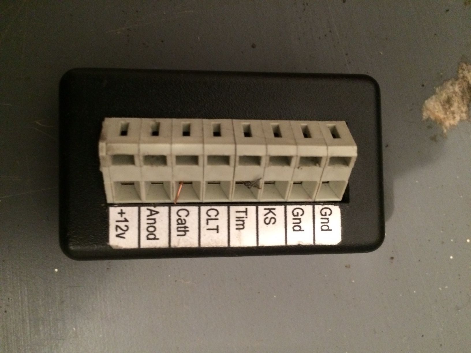
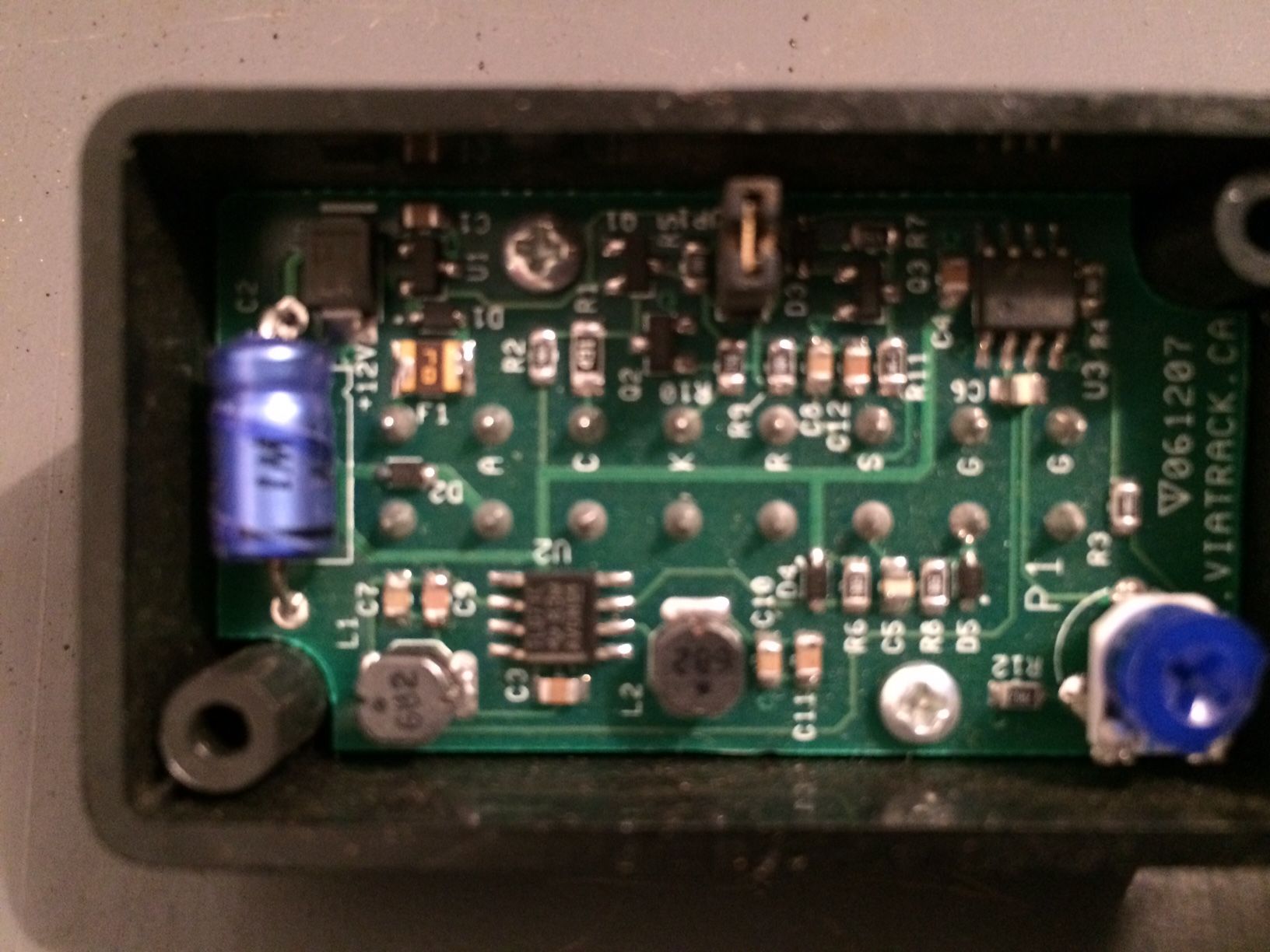
the other device is a KnocksenseMS unit.
The green Spare 3 wire probably connected directly to the MS2 CPU, I believe he was sending the knock sensor signal to it. Did this come with a harness?
my advice is:Stop moving wires around.
the other device is a KnocksenseMS unit.
The green Spare 3 wire probably connected directly to the MS2 CPU, I believe he was sending the knock sensor signal to it. Did this come with a harness?
Last edited by Braineack; Mar 9, 2016 at 08:33 AM.
Reply
0
0
Maybe abeFM or Frank or Thirdgen. Something about it looks familiar.
Reply
0
0
Supporting Vendor

Joined: Sep 2006
Posts: 2,332
Total Cats: 67
Yes, there are a couple features that match how we do prebuilt V3.0 boards (all components included, the use of hot glue on the plastic screws) but it definitely wasn't modified by us. Hard to get a positive ID on the mods as there's so much spaghetti wiring going on.
Reply
0
0


Thread
Thread Starter
Forum
Replies
Last Post
curly
Build Threads
492
Aug 9, 2018 02:34 PM
gtiracer06
Cars for sale/trade
6
Apr 2, 2016 02:04 PM


