
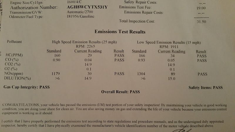
Help me pass emissions


Dude ....
If you in fact have a DC offset as indicated in the plots you posted, you need to figure out why. You are looking for the noise artifact (AC) but ignoring the apparent DC bias across the MS3. The noise is almost certainly due to currents from a switch mode controller in the WB or ECU (as indicated by the change in DC during KOEO).
If you in fact have a DC offset as indicated in the plots you posted, you need to figure out why. You are looking for the noise artifact (AC) but ignoring the apparent DC bias across the MS3. The noise is almost certainly due to currents from a switch mode controller in the WB or ECU (as indicated by the change in DC during KOEO).
Reply
 0
0

0

Thread Starter
Junior Member
Joined: Mar 2010
Posts: 172
Total Cats: 20
From: Melissa, TX
I'm not sure what you are seeing, but the is no measurable bias between chassis ground and analog ground, measured at the lc2 or db37 or the oem harness. The bias is if you measure from any of those locations to the floor pan, or the ground in the engine bay. Its why I am investigating the grounding. I wouldn't be suprised to find that there is crap continuity between pins 3A-3D to their ground point. My POS multimeter isn't good enough to evaluate grounds, but finding the ECU floating 1.1V above the chassis indicates that the grounds are not great.
Reply
0
0

you can calibrate out volt bias.
If i were wiring it, I'd run all the sensor grounds directly back to the MS.
so the TPS, AIT, cam, crank, etc. all the ground wires go back to the MS and ground at the ECU itself.
then I'd run as many wires from the MS to the main ground point on the fuel rail as possible from the ECU harness.
sensors should ground at the same point as the ECU, not the head.
you should refer to this: MS3XV30_Hardware-1.4 page 13
where you are trying to pretty much doing this: MS3XV30_Hardware-1.4 page 14
here, again note the sensor grounds: MS3XV30_Hardware-1.4 page 17
Reply
0
0
Thread Starter
Junior Member
Joined: Mar 2010
Posts: 172
Total Cats: 20
From: Melissa, TX
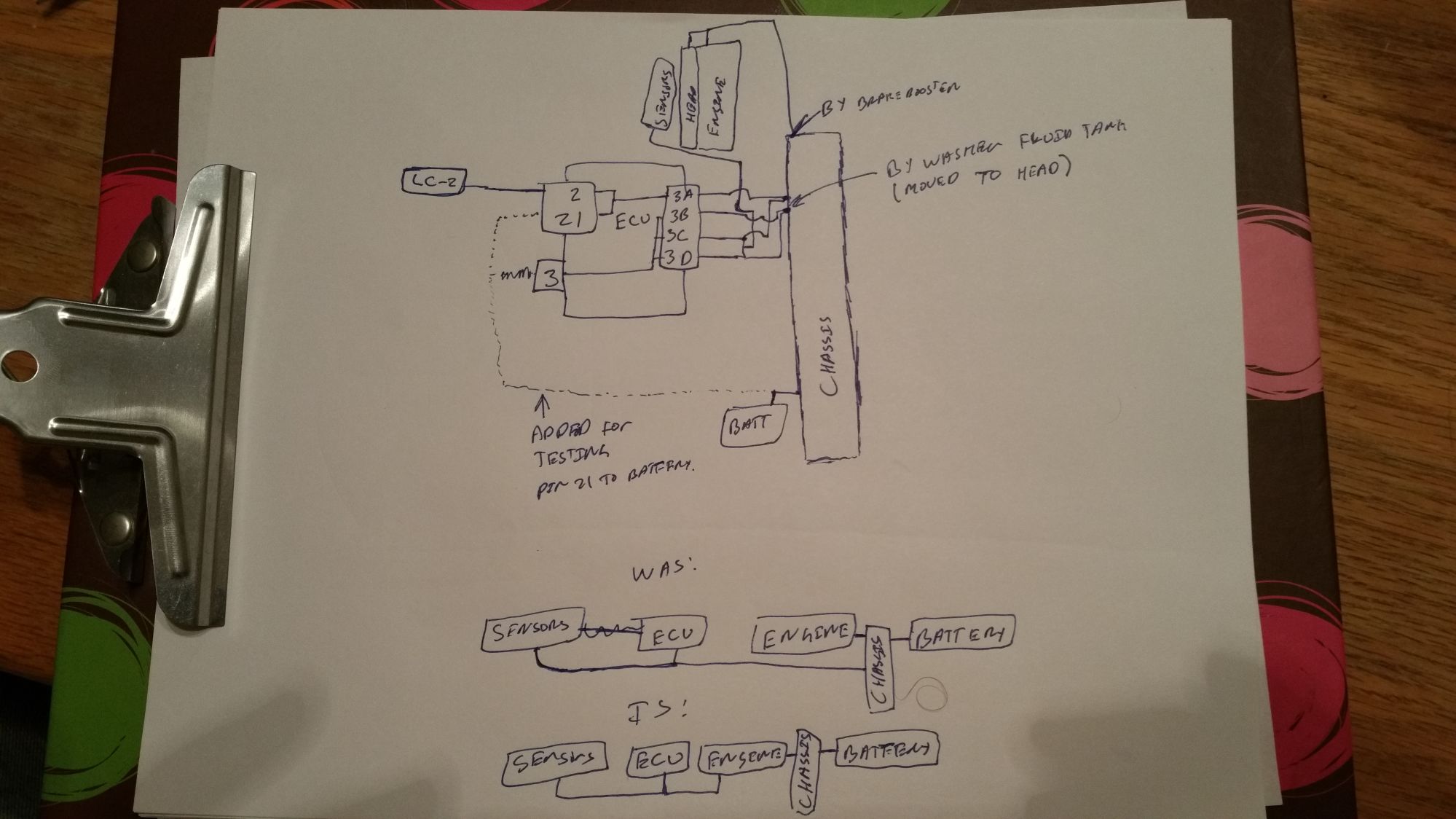
What we have here is a failure to communicate. I'll sketch up what I've seen and post it. The key is the ECU and sensors are all grounding at the same place, I just moved that spot from the chassis to the head. So that that whole plane will sit atop the engine like in your "correct" picture, rather than going around the engine back to the battery.
Reply
0
0
Thread Starter
Junior Member
Joined: Mar 2010
Posts: 172
Total Cats: 20
From: Melissa, TX
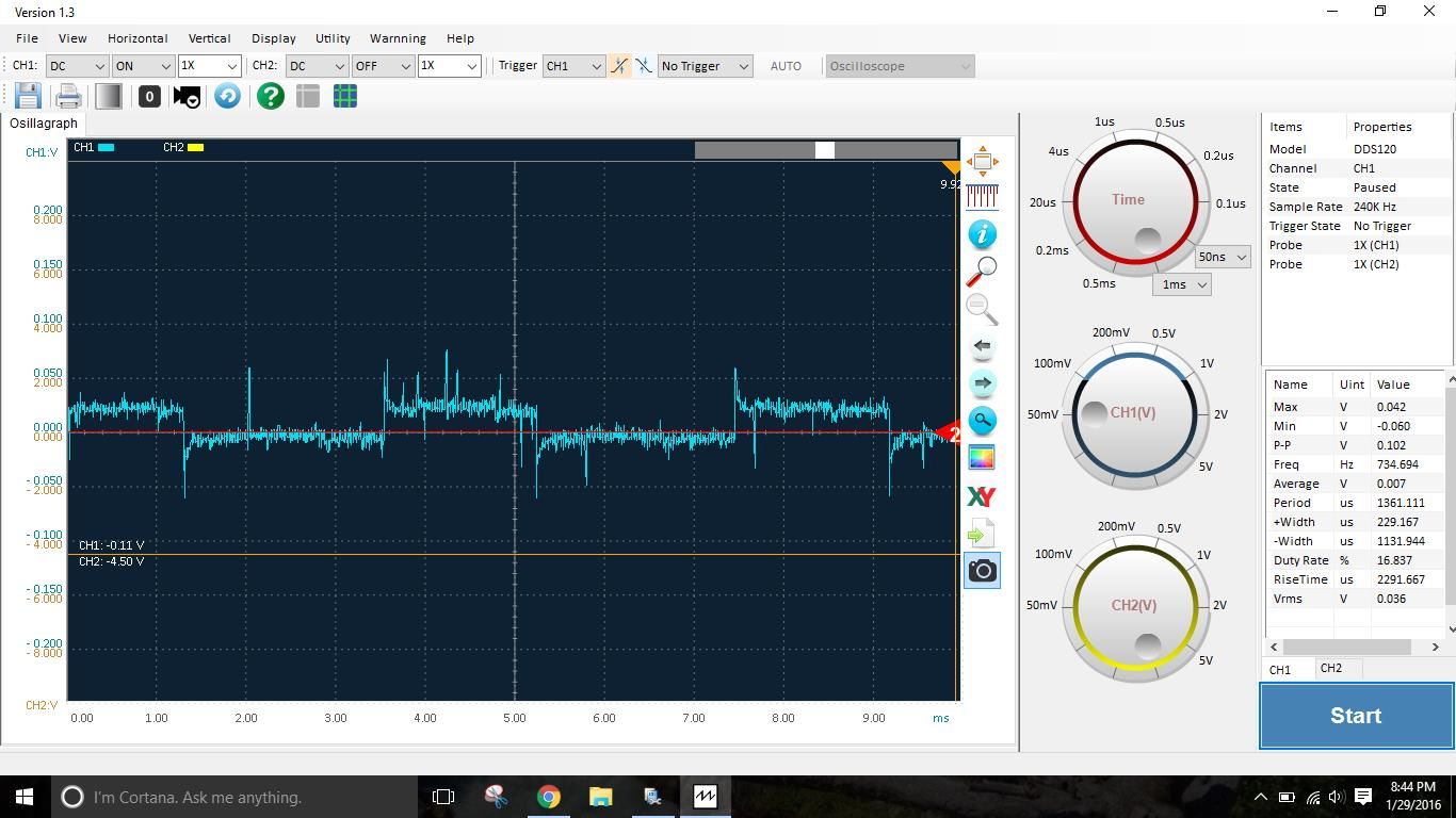
So as requested I verified that the source of the oscillation is in the ECU. Its the one dumping the oscillation into the ground. As to how I sorted that out..
I disconnected the LC2 (the entire DB-37) connnector from the ECU then monitored the ground relative to the new wire I ran from the battery. Noise is present on the DB37 Pin 2.

Next I disconnected pin 3A, and grounded the ECU to the battery through pin 21 on the DB-37. Still showed noise, though it doesn't look the same. I also checked the end of the disconnected Pin 3A relative to the digital ground and found it nice and clean.
Pin 21 ground wire relative to digital ground
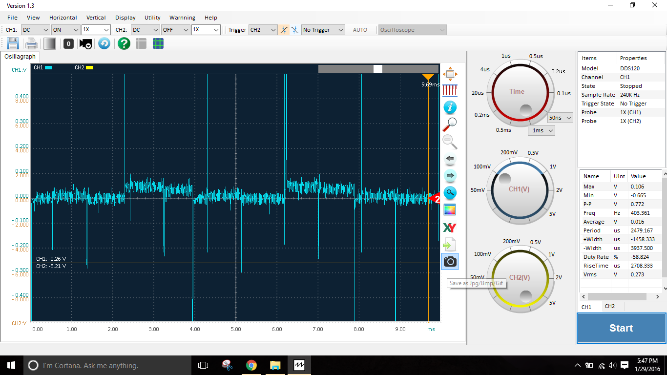
Disconnected pin 3A relative to digital ground

I was reluctant to test this because now what? I have no idea how to troubleshoot why the ECU is putting this oscillation on the ground, particularly with the key on and engine off. The only PWM that should be running is the IAC, and disconnecting it before didnt resolve the issue, but maybe I need to disconnect and disable it? Even the loop for it was the issue, how would I fix it?
I disconnected the LC2 (the entire DB-37) connnector from the ECU then monitored the ground relative to the new wire I ran from the battery. Noise is present on the DB37 Pin 2.
Next I disconnected pin 3A, and grounded the ECU to the battery through pin 21 on the DB-37. Still showed noise, though it doesn't look the same. I also checked the end of the disconnected Pin 3A relative to the digital ground and found it nice and clean.
Pin 21 ground wire relative to digital ground
Disconnected pin 3A relative to digital ground
I was reluctant to test this because now what? I have no idea how to troubleshoot why the ECU is putting this oscillation on the ground, particularly with the key on and engine off. The only PWM that should be running is the IAC, and disconnecting it before didnt resolve the issue, but maybe I need to disconnect and disable it? Even the loop for it was the issue, how would I fix it?
Reply
0
0
Thread Starter
Junior Member
Joined: Mar 2010
Posts: 172
Total Cats: 20
From: Melissa, TX
Went looking for what function is generating the issue, so I disabled the IAC, which left behind a very clean 255HZ oscillation running at 45% duty cycle (1.8ms high, 2.2ms low)

With the IAC enabled, you can clearly see its 511hz pattern adding ~.044v ontop of the above 255hz one.
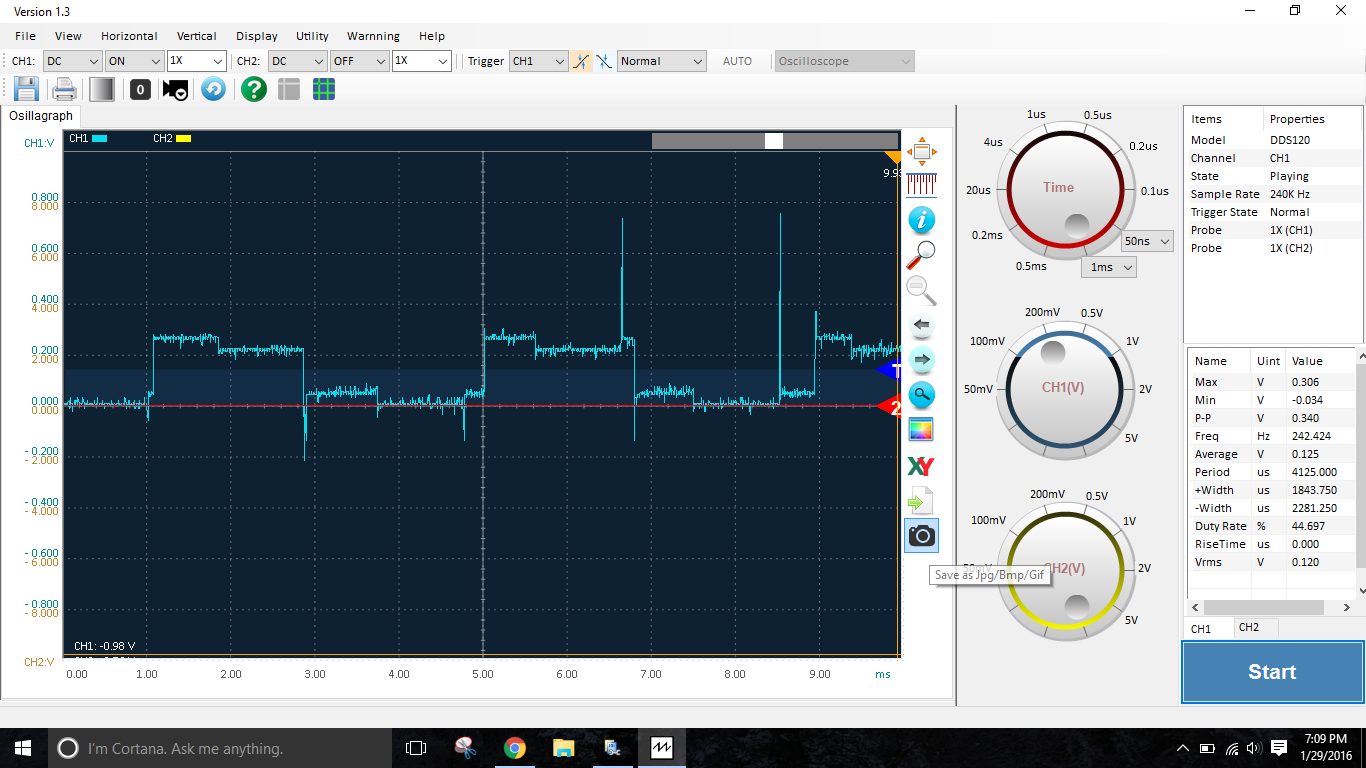
Measuring the same thing on the ground wire @ 3A shows a pretty significant voltage drop between the ECU and the ground wire, with the oscillation at pin 21 running at .22, while the ground wire is at .075v the residual being due to resistance in the ground wire.
In theory I could just let this chassis ground do its thing, thats why you have separate grounds, and just wire the ground for the LC2 into the Harness @ as you were suggesting Brain. The only concern at that point would the LC2 heater crapping up those grounds, but its certainly better than I have now and would only be a concern while the heater is running.
With the IAC enabled, you can clearly see its 511hz pattern adding ~.044v ontop of the above 255hz one.
Measuring the same thing on the ground wire @ 3A shows a pretty significant voltage drop between the ECU and the ground wire, with the oscillation at pin 21 running at .22, while the ground wire is at .075v the residual being due to resistance in the ground wire.
In theory I could just let this chassis ground do its thing, thats why you have separate grounds, and just wire the ground for the LC2 into the Harness @ as you were suggesting Brain. The only concern at that point would the LC2 heater crapping up those grounds, but its certainly better than I have now and would only be a concern while the heater is running.
Reply
1
1
Thread Starter
Junior Member
Joined: Mar 2010
Posts: 172
Total Cats: 20
From: Melissa, TX
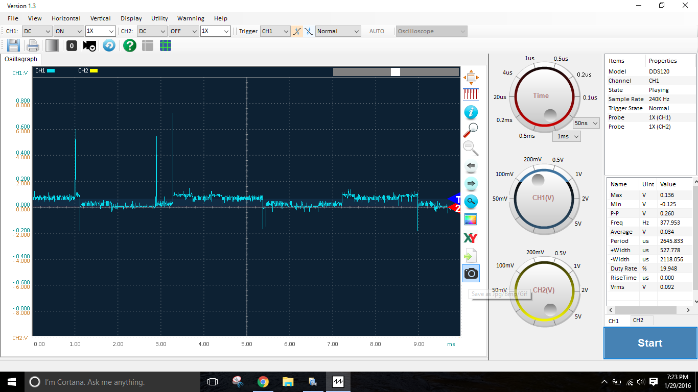
So this is with the LC2 ground hooked into 3C, bypassing the ECU. This ground was previously clean so we can surmise that the oscillation seen here is from the heater. I can read the same thing @ DB37 pin 3. This oscillation is very small however, on the order of .025V (down from .2V), which would be about .07 AFR the way I currently have the ECU scaled, and this is probably worst case since the car is cold. I say its acceptable. I don't like junking up the logic ground, but .025V is nothing really. I monitored with tunerstudio and saw the AFR reading jumping around by .1. I am actually surprised people get logs with it unchanging, considering the sensitivities involved I would expect this to be about par for the course.
Reply
0
0
Thread Starter
Junior Member
Joined: Mar 2010
Posts: 172
Total Cats: 20
From: Melissa, TX
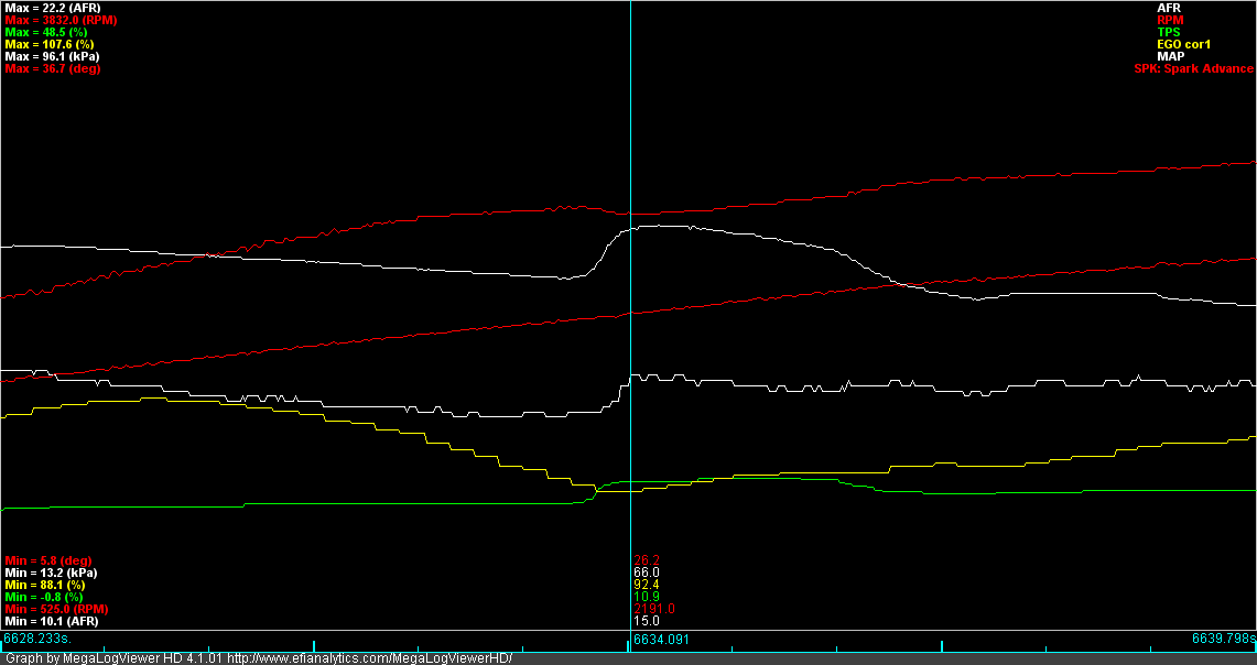
Everything seems to be working ok. Time to go back to the sniffer. Hopefully this doesnt make the NOx pop up high enough to fail, but if it does I will just pull a flat 5* of timing from across the table. It doesn't appear that the TPS or MAP sensors have been negatively impacted. Looking over my log, the next thing to attack will be the acceleration enrichment. Everytime I throttle up the car goes a bit lean, but that is not a topic for this thread.
Reply
0
0
Thread Starter
Junior Member
Joined: Mar 2010
Posts: 172
Total Cats: 20
From: Melissa, TX
I disconnected the LC2 (the entire DB-37) connnector from the ECU then monitored the ground relative to the new wire I ran from the battery. Noise is present on the DB37 Pin 2.
Next I disconnected pin 3A, and grounded the ECU to the battery through pin 21 on the DB-37. Still showed noise, though it doesn't look the same. I also checked the end of the disconnected Pin 3A relative to the digital ground and found it nice and clean.
Pin 21 ground wire relative to digital ground
Reply
0
0
Thread Starter
Junior Member
Joined: Mar 2010
Posts: 172
Total Cats: 20
From: Melissa, TX
Thanks fellas. The only other thing I did was pull 5� of timing from the map everywhere except idle (the car hates idling at 10�) to knock down the NOx. I may or may not have put the timing right back after testing.
Reply
0
0

Thread Starter
Junior Member
Joined: Mar 2010
Posts: 172
Total Cats: 20
From: Melissa, TX
The really load it up though. The test is run at about 60kpa, so it works out for cruising at a higher speed in 5th, but due to my gearing the rpms the test is run at is too low. I think they would rather run at a higher load and lower speed. They don't strap the car on the dyno, just chock it, I wouldn't want them to run it at a high speed
Reply
0
0

Thread
Thread Starter
Forum
Replies
Last Post
x_25
Build Threads
105
Nov 24, 2020 07:31 PM
ahaidet
Miata parts for sale/trade
12
Apr 5, 2016 09:42 AM
itsMikey
MEGAsquirt
11
Jan 15, 2016 09:27 AM
f1luva92
MEGAsquirt
13
Feb 10, 2008 10:09 PM


