I do not understand the CKP/CMP relationship apparently
 01-10-2012, 05:03 PM
#1
Tour de Franzia

Thread Starter
iTrader: (6)
Join Date: Jun 2006
Location: Republic of Dallas
Posts: 29,085
Total Cats: 375
I hope I'm not the only one with this problem.
Test case:
Let's pretend you have a 1994 chassis car, a VVT engine, a 2001 hall sensor, TSE 12-tooth wheel, and the CMP from the 2001 engine.
Things I don't totally understand:
this screen:

specifically:
In Toothed Wheel it should always be set to zero - use tooth#1 angle instead.
okay
Use cam signal if available - This is NOT used in "Toothed wheel" mode. A few other wheel modes require this to indicate that the cam sensor should be used. It will be removed in a future release.
okay
Cam input - Either MS3X or JS10. The MS3X input is ready to use. JS10 requires DIY board customisation.
okay
Tooth #1 Angle: Can this be measured with a protractor or should it be more accurate and use a real time wheel? (What is this value for a stock NB CKP wheel?)
Where do we enter CMP tooth position? on this screen? Is the CMP location non-negotiable in regards to falling immediately before CKP tooth #1?
Some history:
Just once, but apparently I didn't put two and two together.
I don't understand why. Why am I required to run a 12-1 CKP if I have a single-tooth CMP? It seems logical to me that I can use a single tooth CMP to indicate position.
Why not run the 12-tooth wheel for less scatter?
Got it.
Other questions for my 1991:
Test case:
Let's pretend you have a 1994 chassis car, a VVT engine, a 2001 hall sensor, TSE 12-tooth wheel, and the CMP from the 2001 engine.
Things I don't totally understand:
- Which tooth to cut off from my 12-tooth wheel to convert to 12-1? As I read this, it's dependent upon CMP tooth position.
- Do I really need to cut off a tooth? http://www.msextra.com/doc/ms3/trigg...lwheelcrankcam It appears to me that a 12-tooth CKP has enough of a gap between teeth to use the single-tooth CMP together.
- Can I retard or advance the 2001 cam too much with VVTuner to screw this up?
this screen:
specifically:
In Toothed Wheel it should always be set to zero - use tooth#1 angle instead.
okay
Use cam signal if available - This is NOT used in "Toothed wheel" mode. A few other wheel modes require this to indicate that the cam sensor should be used. It will be removed in a future release.
okay
Cam input - Either MS3X or JS10. The MS3X input is ready to use. JS10 requires DIY board customisation.
okay
Tooth #1 Angle: Can this be measured with a protractor or should it be more accurate and use a real time wheel? (What is this value for a stock NB CKP wheel?)
Where do we enter CMP tooth position? on this screen? Is the CMP location non-negotiable in regards to falling immediately before CKP tooth #1?
Some history:
Just once, but apparently I didn't put two and two together.
Why not run the 12-tooth wheel for less scatter?
Other questions for my 1991:
- Why can't I run a 12 tooth CKP and 1 tooth CMP (modified CAS from Y8s) using MS1?
- Can MSpnp9093 send an RPM signal to my tach?
- When will I finally put MS3 on my turbo car?

Reply
 0
0

0
01-10-2012, 05:14 PM
#2
Boost Pope

iTrader: (8)
Join Date: Sep 2005
Location: Chicago. (The less-murder part.)
Posts: 33,039
Total Cats: 6,604
I'll re-post what I wrote in the other thread, but first, some Cliff's Notes:
1: You do not need a missing tooth on the crank if you have any kind of useful cam reference at all. Missing crank teeth are used to compensate for the lack of a cam signal.
2: The combination of a 12T crankwheel and an UNMODIFIED NB cam signal cannot be used. It would be theoretically possible, however there is no software support for it and this is a more complex configuration than can be defined in the "generic wheel" menu.
3: A 12T crankwheel PROBABLY cannot be used with VVT. I'd have to do some measuring to be certain, however I'm pretty sure that the teeth on a 12T wheel are too closely spaced, and that the range of motion of the VVT actuator would cause the cam pulses to cross over a crank pulse.
Now, the repost:
Running a 12T wheel on an NB, you have two basic options:
1: Cut off one tooth (thus creating a 12-1 wheel) and run with no cam signal at all. This is essentially the same as my old setup with the 36-1 crankwheel.
You will be limited to batch injection and ignition in this mode, as you don't have an absolute cycle reference. In other words, without a cam signal, the ECU can't tell whether the #1 cylinder is at TDC on the exhaust/intake cycle or the compression/ignition cycle. And, of course, no VVT.
2: Leave all of the teeth in place, and modify the intake cam pulley (for '99-'00) or the intake cam itself (for '01-'05) to remove two of the three teeth, so that you have one pulse per cam revolution on the second sensor. This will enable you to run fully sequential spark and fuel, however this configuration will most likely not allow closed-loop VVT to work, as the crank teeth are too closely spaced, and the cam pulses will therefore cross over crank pulses as the cam advances.
IN THEORY you should be able to run a 12T crankwheel with a stock NB-style cam signal, however there is no SOFTWARE SUPPORT for such a configuration at present. Configuring the ECU to understand such a signal is a more complex task than can be achieved with the "generic wheel" configuration table, and it would thus require a custom configuration within the software itself, such as the ones which were done to support Neon/420A, Subaru 6/7, Mitsu 4G63 or '99+ Miata sensor pairings in the MS2. (In other words, the ones where you just select "99+ Miata" from a drop-down window, rather than manually keying in all the tooth data.)
So, long story short: The 12T wheel is an excellent upgrade for NA owners looking to eliminate their dependence on the CAS, and is a moderate upgrade for '99-'00 owners looking to slightly improve the accuracy of the spark prediction. For owners of VVT engines, however, there are some serious disadvantages which outweigh any potential benefits.
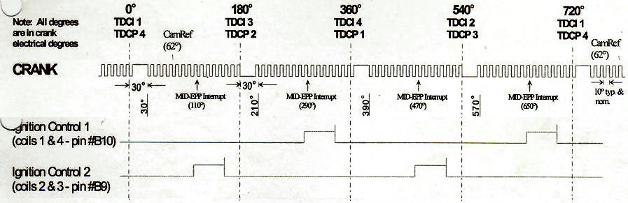
On '90-'93 engines, there is an igniter seperate from the coilpack, and this generates the signal to drive the tachometer in the instrument cluster. On '94-'95.5 engines, the igniter is integrated into the coils, and the tachometer signal is generated here. On '95.5 and later engines, the igniter is still integrated into the coils, however the tach signal is produced by the ECU.
If you convert to sequential spark, then by definition you are not using the stock ignition coils.
If you have a '95.5 or later car, this does not matter, as your tach signal was not in any way related to the ignition system to begin with. The ECU will continue to generate the tach signal just as it did before.
If you have a '90-'95.5 car, you will need to run a new wire from the ECU to the wire that drives the tachometer in the instrument cluster, and have the ECU start generating the tach signal just like it would in a later car.
In either case, it does not matter how many teeth are on the wheel, or whether you are using one wheel or two, or whether you are using two coils or four. The ECU simply generates one pulse on the tachometer output pin for every ignition event.
Each of your two ignition coils has one tachometer output pin which is driven by the coil's internal igniter. These two outputs are wired in parallel to the tachometer. Every time an ignition coil fires, it generates a pulse on the tach output pin. The summing together these two lines means that the tachometer sees one pulse every time either coil fires.
Right here, good buddy. 
1: You do not need a missing tooth on the crank if you have any kind of useful cam reference at all. Missing crank teeth are used to compensate for the lack of a cam signal.
2: The combination of a 12T crankwheel and an UNMODIFIED NB cam signal cannot be used. It would be theoretically possible, however there is no software support for it and this is a more complex configuration than can be defined in the "generic wheel" menu.
3: A 12T crankwheel PROBABLY cannot be used with VVT. I'd have to do some measuring to be certain, however I'm pretty sure that the teeth on a 12T wheel are too closely spaced, and that the range of motion of the VVT actuator would cause the cam pulses to cross over a crank pulse.
Now, the repost:
1: Cut off one tooth (thus creating a 12-1 wheel) and run with no cam signal at all. This is essentially the same as my old setup with the 36-1 crankwheel.
You will be limited to batch injection and ignition in this mode, as you don't have an absolute cycle reference. In other words, without a cam signal, the ECU can't tell whether the #1 cylinder is at TDC on the exhaust/intake cycle or the compression/ignition cycle. And, of course, no VVT.
2: Leave all of the teeth in place, and modify the intake cam pulley (for '99-'00) or the intake cam itself (for '01-'05) to remove two of the three teeth, so that you have one pulse per cam revolution on the second sensor. This will enable you to run fully sequential spark and fuel, however this configuration will most likely not allow closed-loop VVT to work, as the crank teeth are too closely spaced, and the cam pulses will therefore cross over crank pulses as the cam advances.
IN THEORY you should be able to run a 12T crankwheel with a stock NB-style cam signal, however there is no SOFTWARE SUPPORT for such a configuration at present. Configuring the ECU to understand such a signal is a more complex task than can be achieved with the "generic wheel" configuration table, and it would thus require a custom configuration within the software itself, such as the ones which were done to support Neon/420A, Subaru 6/7, Mitsu 4G63 or '99+ Miata sensor pairings in the MS2. (In other words, the ones where you just select "99+ Miata" from a drop-down window, rather than manually keying in all the tooth data.)
So, long story short: The 12T wheel is an excellent upgrade for NA owners looking to eliminate their dependence on the CAS, and is a moderate upgrade for '99-'00 owners looking to slightly improve the accuracy of the spark prediction. For owners of VVT engines, however, there are some serious disadvantages which outweigh any potential benefits.
I always thought the tach was driven off of the coils on <=1994 cars.
I also don't understand what this does to the tach when we convert to sequential spark.
If you have a '95.5 or later car, this does not matter, as your tach signal was not in any way related to the ignition system to begin with. The ECU will continue to generate the tach signal just as it did before.
If you have a '90-'95.5 car, you will need to run a new wire from the ECU to the wire that drives the tachometer in the instrument cluster, and have the ECU start generating the tach signal just like it would in a later car.
In either case, it does not matter how many teeth are on the wheel, or whether you are using one wheel or two, or whether you are using two coils or four. The ECU simply generates one pulse on the tachometer output pin for every ignition event.
What actually sends the signal to the tach in my 1994? The firing of the igniter?
Where can I find answers to stupid questions like these?
Last edited by Joe Perez; 01-10-2012 at 05:32 PM.
Reply
0
0
01-10-2012, 05:31 PM
#4
Tour de Franzia
Thread Starter
iTrader: (6)
Join Date: Jun 2006
Location: Republic of Dallas
Posts: 29,085
Total Cats: 375
Joe, please edit my typo quote to read:
does this change things? Although I did this in my original post, I need to focus on one car at a time, lets start with the 2001 engine going into the 1994 running sequential fuel and I will most likely use the 1994 ignition system for now.
I have a factory NB wheel but I have no clue how to set-up MS for a wheel with uneven tooth spacing.
I have a factory NB wheel but I have no clue how to set-up MS for a wheel with uneven tooth spacing.
Reply
0
0
01-10-2012, 05:43 PM
#5
Tour de Franzia
Thread Starter
iTrader: (6)
Join Date: Jun 2006
Location: Republic of Dallas
Posts: 29,085
Total Cats: 375
2: Leave all of the teeth in place, and modify the intake cam pulley (for '99-'00) or the intake cam itself (for '01-'05) to remove two of the three teeth, so that you have one pulse per cam revolution on the second sensor. This will enable you to run fully sequential spark and fuel, however this configuration will most likely not allow closed-loop VVT to work, as the crank teeth are too closely spaced, and the cam pulses will therefore cross over crank pulses as the cam advances.
Thanks. I feel like this is a rudimentary concept that should be covered somewhere. I suppose if I read these sections of the manual over and over and don't get it, the bandwidth is justified.
Reply
0
0
01-10-2012, 05:50 PM
#6
Tour de Franzia
Thread Starter
iTrader: (6)
Join Date: Jun 2006
Location: Republic of Dallas
Posts: 29,085
Total Cats: 375
Here's another really dumb question, and although I assume this is somehow written into the CKP algorithm in regards to counting teeth....
How does the computer know when it's crossing over a missing tooth? When I remove a tooth for my 1991, which is the best to grind off and why?
How does the computer know when it's crossing over a missing tooth? When I remove a tooth for my 1991, which is the best to grind off and why?
Reply
0
0
01-10-2012, 05:51 PM
#7
Boost Pope
iTrader: (8)
Join Date: Sep 2005
Location: Chicago. (The less-murder part.)
Posts: 33,039
Total Cats: 6,604
By 12+1, I assume you mean a 12T crank and a 1T cam signal?
If so, then yes, any wheel configuration that uses evenly-spaced teeth with no more than one gap (of any length) in the primary signal can be accommodated by any version of the MS including the MS1. Configurations such as this are actually quite simple, and are specified in the "generic wheel" menu. In fact, something like a 12+1 or 36+1 combo is just about the simplest possible configuration. You tell it how many teeth are on the crank, what angle the cam tooth is at, and that's all.
Where you get into problems is when you have wheels with unevenly-spaced teeth. The stock NB patterns are unevenly spaced on both the crank and the cam, which is becoming quite common in OEM designs. The CPU (MS2/3 only) is perfectly capable of handling situations like this, however there's no good way to describe such a pattern to it given the relatively simple design of the user interface. So to support cars like this, the core software contains many "special" configurations already pre-defined for all of these different oddball OEM patterns, and the user can simply select the appropriate one from a drop-down menu.
It changes nothing.
The sensors themselves don't matter. If you wanted to, you could fabricate mounts to point the crank sensor from a Suzuki motorcycle at the crankwheel and the shaft-position sensor from an industrial printing press at the camshaft, and it would work just fine.
What matters is the pattern of teeth on the wheel(s). You can't create oddball pattern combinations (such as 12T crank and NB cam) and expect them to work- there's no way to define such a thing in the software. You also can't use a crankwheel which has teeth so closely spaced together that the cam pulse(s) cross over them as the VVT mechanism operates. What I mean by that is this:
Take a stock NB crankwheel, which has four teeth. And a stock NB camwheel which has three teeth, arranged as a single tooth, followed 180� by a pair of teeth.
The arrangement of all of these teeth is such that regardless of how far the cam is advanced or retarded, the pulses coming off the cam sensor are always going to occur between the second and third teeth on the crankwheel. (I'm actually not sure about the exact numbers, i'm just using the second and third teeth as an example.) At full retard, the cam pulse(s) will occur just before the third crank tooth, and at full advance, the cam pulse(s) will occur just after the second crank tooth, but they will ALWAYS fall somewhere within that range.
The problem, therefore, is that as you start adding more teeth to the crank, it no longer becomes possible to ensure that the cam pulse(s) will always occur between the same two teeth on the crank. And this situation cannot be accommodated- in order to properly phase the engine, the cam reference must always occur within the space between two specific teeth on the crank. It can move around within the free space between those two teeth, but it can never go outside of that space.
If so, then yes, any wheel configuration that uses evenly-spaced teeth with no more than one gap (of any length) in the primary signal can be accommodated by any version of the MS including the MS1. Configurations such as this are actually quite simple, and are specified in the "generic wheel" menu. In fact, something like a 12+1 or 36+1 combo is just about the simplest possible configuration. You tell it how many teeth are on the crank, what angle the cam tooth is at, and that's all.
Where you get into problems is when you have wheels with unevenly-spaced teeth. The stock NB patterns are unevenly spaced on both the crank and the cam, which is becoming quite common in OEM designs. The CPU (MS2/3 only) is perfectly capable of handling situations like this, however there's no good way to describe such a pattern to it given the relatively simple design of the user interface. So to support cars like this, the core software contains many "special" configurations already pre-defined for all of these different oddball OEM patterns, and the user can simply select the appropriate one from a drop-down menu.
The sensors themselves don't matter. If you wanted to, you could fabricate mounts to point the crank sensor from a Suzuki motorcycle at the crankwheel and the shaft-position sensor from an industrial printing press at the camshaft, and it would work just fine.
What matters is the pattern of teeth on the wheel(s). You can't create oddball pattern combinations (such as 12T crank and NB cam) and expect them to work- there's no way to define such a thing in the software. You also can't use a crankwheel which has teeth so closely spaced together that the cam pulse(s) cross over them as the VVT mechanism operates. What I mean by that is this:
Take a stock NB crankwheel, which has four teeth. And a stock NB camwheel which has three teeth, arranged as a single tooth, followed 180� by a pair of teeth.
The arrangement of all of these teeth is such that regardless of how far the cam is advanced or retarded, the pulses coming off the cam sensor are always going to occur between the second and third teeth on the crankwheel. (I'm actually not sure about the exact numbers, i'm just using the second and third teeth as an example.) At full retard, the cam pulse(s) will occur just before the third crank tooth, and at full advance, the cam pulse(s) will occur just after the second crank tooth, but they will ALWAYS fall somewhere within that range.
The problem, therefore, is that as you start adding more teeth to the crank, it no longer becomes possible to ensure that the cam pulse(s) will always occur between the same two teeth on the crank. And this situation cannot be accommodated- in order to properly phase the engine, the cam reference must always occur within the space between two specific teeth on the crank. It can move around within the free space between those two teeth, but it can never go outside of that space.
Reply
0
0
01-10-2012, 05:56 PM
#8
Boost Pope
iTrader: (8)
Join Date: Sep 2005
Location: Chicago. (The less-murder part.)
Posts: 33,039
Total Cats: 6,604
It works because the teeth on the '01+ crank and cam are laid out such that no matter what position the camshaft is in, its pulse(s) always occur between two specific teeth on the crank. This is possible because the gap between the teeth on the crank is wider than the range of motion of the VVT system.
Regardless of the year of the car, in order to run VVT you must use the stock '01+ crank and cam wheels. The NA-style CAS is not used in such configurations.
So, imagine that you see this:
5ms - 5ms - 10ms - 5ms - 5ms - 5ms - 5ms - 5ms - 5ms -
It's a pretty safe bet that the third tooth was missing.
Reply
1
1
01-10-2012, 05:59 PM
#9
Tour de Franzia
Thread Starter
iTrader: (6)
Join Date: Jun 2006
Location: Republic of Dallas
Posts: 29,085
Total Cats: 375
By 12+1, I assume you mean a 12T crank and a 1T cam signal?
If so, then yes, any wheel configuration that uses evenly-spaced teeth with no more than one gap (of any length) in the primary signal can be accommodated by any version of the MS including the MS1. Configurations such as this are actually quite simple, and are specified in the "generic wheel" menu. In fact, something like a 12+1 or 36+1 combo is just about the simplest possible configuration. You tell it how many teeth are on the crank, what angle the cam tooth is at, and that's all.
If so, then yes, any wheel configuration that uses evenly-spaced teeth with no more than one gap (of any length) in the primary signal can be accommodated by any version of the MS including the MS1. Configurations such as this are actually quite simple, and are specified in the "generic wheel" menu. In fact, something like a 12+1 or 36+1 combo is just about the simplest possible configuration. You tell it how many teeth are on the crank, what angle the cam tooth is at, and that's all.
What benefits exist for the 12-1 CKP and 1-tooth CMP on my turbo 1.6 chassis? Right now I'm really tempted to go home, cut a tooth off the TSE wheel, put it on my 1991 car, use a tach-output from MS1, and see what it does.
Reply
0
0
01-10-2012, 05:59 PM
#10
Former Vendor
iTrader: (31)

Join Date: Nov 2006
Location: Sunnyvale, CA
Posts: 15,442
Total Cats: 2,100
No, a 12+1 crank wheel, with an added tooth instead of a missing tooth. The AEM can be told where to look for the added tooth, and it will sync based on the pattern of the added tooth and the factory cam wheel teeth. We do it this way on the AEM because removing a tooth causes the AEM (at least the Gen1) to skip the other 5 sister teeth of the missing one, thus turning the wheel into a 6-tooth wheel.
This is how I get around the crossover issue with the AEM boxes - 12+1 wheel and factory sensors. Works great.
This is how I get around the crossover issue with the AEM boxes - 12+1 wheel and factory sensors. Works great.
Reply
0
0
01-10-2012, 06:17 PM
#11
Boost Pope
iTrader: (8)
Join Date: Sep 2005
Location: Chicago. (The less-murder part.)
Posts: 33,039
Total Cats: 6,604
No, a 12+1 crank wheel, with an added tooth instead of a missing tooth. The AEM can be told where to look for the added tooth, and it will sync based on the pattern of the added tooth and the factory cam wheel teeth. We do it this way on the AEM because removing a tooth causes the AEM (at least the Gen1) to skip the other 5 sister teeth of the missing one, thus turning the wheel into a 6-tooth wheel.
Within the MS world, we don't have this problem of being unable to deal with a single missing tooth. In fact, missing-tooth wheels are probably the most common configuration here, owing to the inexplicable popularity of the dreadful Ford EDIS system and the MS's origins within the ole' American Iron community. Those cars used a 36-1 crank wheel, and created a sort of de-facto standard for all kinds of aftermarket wheels to follow.
Reply
0
0
01-10-2012, 06:19 PM
#12
Boost Pope
iTrader: (8)
Join Date: Sep 2005
Location: Chicago. (The less-murder part.)
Posts: 33,039
Total Cats: 6,604
But again, you do not need to cut a tooth off of the crank wheel IF you have a cam signal. Removing a tooth from the crankwheel is done to compensate for the absence of a cam signal in situations where one is not available.
Reply
1
1
01-10-2012, 07:56 PM
#13
Tour de Franzia
Thread Starter
iTrader: (6)
Join Date: Jun 2006
Location: Republic of Dallas
Posts: 29,085
Total Cats: 375
Can you show me what the wheel decoder settings for MS1 will look like with a 12-1? I may do this after the Houston race.
If you had a 12 tooth wheel and a single-tooth CAS in the garage, would you grind a tooth off the CKP wheel or run the 12 tooth CKP + the 1 tooth CMP?
If you had a 12 tooth wheel and a single-tooth CAS in the garage, would you grind a tooth off the CKP wheel or run the 12 tooth CKP + the 1 tooth CMP?
Reply
0
0
01-10-2012, 10:14 PM
#14
Boost Pope
iTrader: (8)
Join Date: Sep 2005
Location: Chicago. (The less-murder part.)
Posts: 33,039
Total Cats: 6,604
(Note that it's been a while since I've had to configure one of these, and I've had a few drinks at this point in the evening.)
Note that if you built and configured your MS according to DIY's instruction for an NA using the CAS, they have everything completely backwards in their documentation with regard to the CAS configuration as well as the fuel and spark wiring. If you configure your system as per the above, it will be "correct", and the engine will not run until you un-reverse the fuel and spark wires.
If you had a 12 tooth wheel and a single-tooth CAS in the garage, would you grind a tooth off the CKP wheel or run the 12 tooth CKP + the 1 tooth CMP?
With an MS2/3, I'd leave the tooth in place and run a cam signal so that I could run sequential.
Last edited by Joe Perez; 01-12-2012 at 12:02 AM. Reason: Too much rum
Reply
2
2
01-11-2012, 08:56 AM
#15
Tour de Franzia
Thread Starter
iTrader: (6)
Join Date: Jun 2006
Location: Republic of Dallas
Posts: 29,085
Total Cats: 375
I owe you several beers, maybe dinner. Seriously, thank you sooooooo much.
I have that same all sensor at home right now, but it's not in the car, lolol.
I have that same all sensor at home right now, but it's not in the car, lolol.
Reply
0
0
01-11-2012, 12:01 PM
#16
Elite Member

Join Date: Jul 2005
Posts: 6,420
Total Cats: 84
If the MS is like the AEM :
It will look at the cadence of the teeth to find the extra or missing one to figure out TDC, a 12+1 works much better than 12-1 during cranking. Especially if the extra tooth comes about 1/3rd of the way after the last one (it's closer to the last one). This is how the K20 has its extra tooth. I know I tested it. The reason is that when cranking with a weak battery the engine's compression causes the RPM to fluctuate, making it difficult to find the missing tooth. The extra tooth when close to the last one, is clearer.
And the choice of which tooth to remove or where to add the extra one matters too when you have VVT. You want the missing tooth or extra tooth to be nowhere near the significant cam signal edges through the range of VVT motion. If it does, the sync algorithm can get lost.
Lastly you don't want a missing tooth to appear just before your normal ignition firing range. You want it just after TDC. When a tooth is missing the software isn't updated by the crank position. And you want a fresh update right about the time it's fixin' to fire a plug.
Reply
0
0
01-11-2012, 02:01 PM
#17
Boost Pope
iTrader: (8)
Join Date: Sep 2005
Location: Chicago. (The less-murder part.)
Posts: 33,039
Total Cats: 6,604
In general, terms like "X+Y" in describing a trigger setup are, within the MS community, used to describe wheels such as those used in the newer Neons where the trigger remains high for a period of time greater than one tooth. Here's an example of a 36-2+2 configuration as per the MSExtra documentation:
It's possible that some configurations involving the K20 description of an "extra" tooth might be hard-coded into it via the vehicle-specific settings somewhere (this would be fundamentally quite similar to the cam signal on an NB), but in general, missing-tooth wheels, in addition to being commonly used in OEM applications (Ford, BMW, Subaru, Renaut) are by far the most widely used non-OEM configuration, not just within the Megasquirt community but in general. A quick Google search for Crank Trigger Wheels turns up all sorts of missing-tooth wheels from vendors representing Electromotive, Motec, Autronic, Haltech, VEMS, Pectel, etc.
The reason is that when cranking with a weak battery the engine's compression causes the RPM to fluctuate, making it difficult to find the missing tooth. The extra tooth when close to the last one, is clearer.
Remember that, in the MS architecture, each gap is compared only to the gap which preceded it, and not to any kind of average. Because acceleration and deceleration of the crankshaft due to compression effort during cranking is a fairly sinusoidal phenomenon, we can assume that crankshaft RPM during the missing tooth has not changed radically since the most recent tooth.
Here's a screenshot of a 60-2 wheel during cranking on a fairly high-compression engine. Each vertical bar represents the time elapsed since the previous trigger:
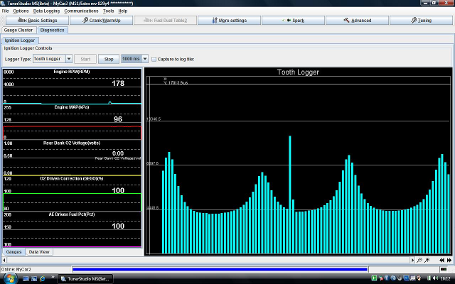
Now, you can clearly see how the crankshaft is slowing down during compression cycles in the form of "peaks", and when looking at the picture in its entirety, it's quite easy to say "well look at that, the missing tooth nearly indistinguishable from those teeth back there near the end of the compression cycles."
However, when you compare the one missing tooth (the sharp spike in the middle) to the tooth pair which preceded it, it's fairly unmistakable. To visualize this from the perspective of the ECU, cut a slit in a piece of paper which is wide enough to expose only two of the bars at a time, place the paper against the screen with the slit exposing two bars, and move it from left to right. If you compare each bar only to the one immediately to the left of it, it becomes clear that this is a relatively foolproof triggering system even on engines with high compression and weak batteries.
Lastly you don't want a missing tooth to appear just before your normal ignition firing range. You want it just after TDC. When a tooth is missing the software isn't updated by the crank position.
And you want a fresh update right about the time it's fixin' to fire a plug.
In the MS1, you must declare a single, specific tooth (well, a pair of them in the case of a 4 cyl engine) to be the "trigger" tooth. The ECU will always start the ignition timer when it sees this tooth. So in the image I made for Hustler above, I have declared tooth #1 (the first tooth after the gap) to be the "trigger" tooth (as well as tooth 7, which is 180� opposite). This gives the ECU a solid reference which is exactly 60� BTDC, sufficiently far away that the spark table will never encroach on it, but not so far away that we're setting the ignition countdown timer higher than it need be.
This is also why, on the MS1, there is really no advantage to increasing the number of teeth on the wheel. No matter how many actual teeth are on the wheel, the ECU only cares about two of them (four, if you use trigger-return for spark during cranking, but that's a bit too advanced for this thread.)
On the MS2 and 3, the system dynamically selects which tooth it will start the trigger on during operation, always selecting the tooth which is nearest to (but still before) the predicted spark angle. So if you have a 36 tooth wheel (one tooth per 10�), the system would trigger on the 20� BTDC tooth for a spark angle between 11� and 20�, on the 30� BTDC tooth for a spark angle between 21� and 30�, on the 40� BTDC tooth for a spark angle between 31� and 40�, etc. As I know you are aware (but others may not be) this reduces the potential for spark inaccuracy due to crankshaft acceleration at high load- selecting a tooth nearest the actual ignition angle minimizes the length of time the ECU has to sit waiting for a timer to run down while blind to any changes in actual crank speed.
For those having trouble understanding the concept, imagine a game in which you have to toss a hamster into a small hole in the ground. Specifically, there are ten holes, in a straight line, spaced 10 feet apart each. With the MS1, you always have to stand at the very first hole to make your throw, regardless of which hole you are aiming for. So hitting the first hole is easy. For the second hole, you have to throw 10 feet. For the third hole, you have to throw 20 feet. by the time you're aiming for the last hole, you have to throw the hamster 90 feet.
With the MS2/3, you're allowed to walk down the field and stand somewhere between the hole you are aiming for and the hole closest to it (the exact distance is pseudo-random, determined by computing the number of seconds elapsed since the last time the word "Obamacare" was uttered on Fox News.) In this scenario, you never have to throw the hamster further than 10 feet, and thus, we would expect your accuracy to improve.
Reply
1
1
01-11-2012, 09:57 PM
#18
Elite Member
Join Date: Jul 2005
Posts: 6,420
Total Cats: 84
36-2 is easy to detect during cranking but 12-1 is harder due to the lower effective sampling rate. I ran the math and it doesn't take much accel or decel to affect it. I looked at actual waveforms and it was problematic w a mediocre battery.
Reply
0
0
01-11-2012, 11:49 PM
#19
Boost Pope
iTrader: (8)
Join Date: Sep 2005
Location: Chicago. (The less-murder part.)
Posts: 33,039
Total Cats: 6,604
EDIT: I edited the image in post # 14 depicting the software settings. You'll need to use Time Based cranking with a 12T wheel and set the trigger returns to 0.
Last edited by Joe Perez; 01-12-2012 at 12:03 AM.
Reply
1
1
01-12-2012, 12:04 AM
#20
Elite Member
Join Date: Jul 2005
Posts: 6,420
Total Cats: 84
You've tried 12-1? Do you have the same cranking plot? Is that cranking plot, zero of the vertical axis, at the bottom? If so the peaks are double the troughs.
Note that with a 36-2 you have 2 missing teeth so the time gap will be 3x normal. Easy to find the missing teeth.
With a 12-1 the missing tooth gap is 2x normal, and it may just be close to the double length gap due to compression.
Trust me the 12-1 took significantly longer to sync and catch than the 12+1 (with the +1 closer to the preceding tooth). It would often mis-sync then lose sync and do it over.
Once it started it was fine. However when blipping in neutral there was a bit of timing error (like 1.5* IIRC) at low RPM, which wasn't there with the 12+1. This is because the AEM only times off of 6 teeth when you have a 12-1.
Reply
0
0


