
Ignition Fail on Dyno!!! Help Please.


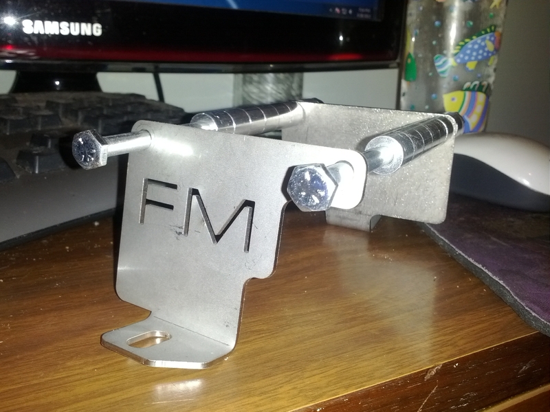
My FM bracket came in today. I will be pictures of it and my coils in a bit.
Reply
 0
0

0
The brackets are actually very simple. Two end pieces with rods to hold all the coils in place. For someone who can do good custom fab work, they would be very easy to replicate. For me who can not fab, they were worth every penny. I should get everything wired up and installed sometime this weekend.
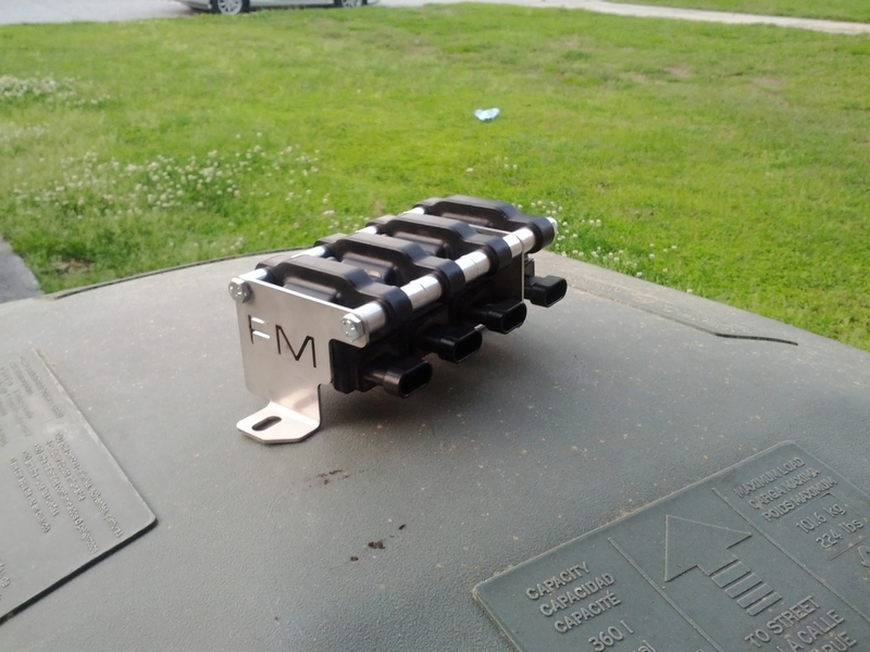
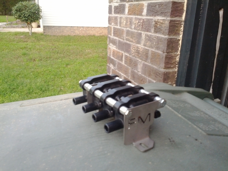
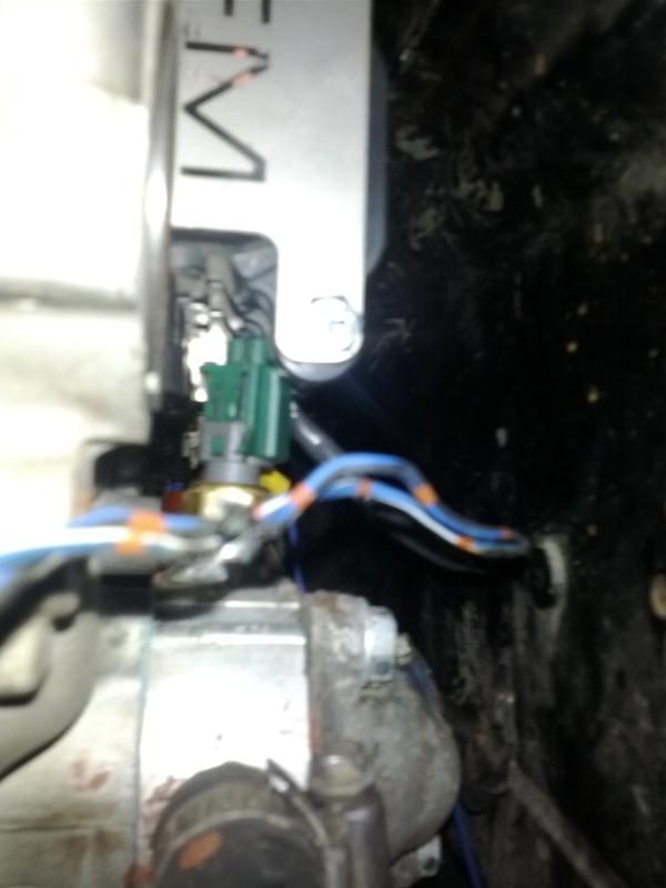
With the coils on it just barely fits with the coolant reroute.
With the coils on it just barely fits with the coolant reroute.
Reply
0
0
Reply
0
0

Thread Starter
Junior Member
Joined: Nov 2009
Posts: 109
Total Cats: 2
From: Dumfries, VA
I have seq. fuel now. Not sure about Shueind.
So, nobody has answered my questions about setup in software or the issue with capacitors and other wiring on physical setup.
Brain, do you have seq spark on your setup?
So, nobody has answered my questions about setup in software or the issue with capacitors and other wiring on physical setup.
Brain, do you have seq spark on your setup?
Reply
0
0
I am running an MS3X so I have sequential fuel and spark on my car. I honestly do not know about what software settings have to be changed or what mods need to be done to the DIYPNP to make it work with sequential spark.
Reply
0
0
IIRC all you gotta do is move whatever's on ALED and WLED to the spark outputs.
PT6 and PT7 are already used for the fuel drivers.
So that leaves you with PA0 for the fan control...I think that's it, so if you dont need any other outputs (like boost or vics or whatnot) you can make it happen.
But don't quote me on it.
PT6 and PT7 are already used for the fuel drivers.
So that leaves you with PA0 for the fan control...I think that's it, so if you dont need any other outputs (like boost or vics or whatnot) you can make it happen.
But don't quote me on it.
Reply
0
0

Thread Starter
Junior Member
Joined: Nov 2009
Posts: 109
Total Cats: 2
From: Dumfries, VA
I think I get it now. Output port settings are only enabled when you want to use the ecu logic to control them as with Knock In on PA0. That's not the case here. Spark output is only through hardware beyond when ALED and WLED are enabled for spark outputs 3 and 4 when single coil is selected instead of wasted spark. ALED and WLED are empty on my board - 99% sure anyways. Only other software settings that matter (other than single coil) are the dwell settings, which I posted previously for the ls2 coils.
Quick logic check. The coil currently feeding cylinders 1 and 4 holds the connector that should be used for cylinder 1, correct. Same thing with coil plug for 2 and 3 feeding the sequential for 2?
Just want to be sure. I'll label them now in that case.
Quick logic check. The coil currently feeding cylinders 1 and 4 holds the connector that should be used for cylinder 1, correct. Same thing with coil plug for 2 and 3 feeding the sequential for 2?
Just want to be sure. I'll label them now in that case.
Reply
0
0
Thread Starter
Junior Member
Joined: Nov 2009
Posts: 109
Total Cats: 2
From: Dumfries, VA
OK, got all my stuff today. I'd post pics but it's identical so far to Shuiend's setup.
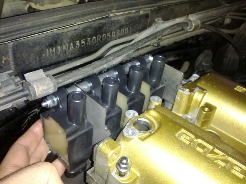
I labeled the harness plug going to Cylinders 1 and 4 as "1" and the harness plug going to cylinders 2 and 3 as "2". Then, I removed the old coil pack and temporarily put the new setup in place. I verified that the stock plug wires will fit this setup if you use 1 to 4 from right to left, which is exactly opposite what FM recommends in their directions (of no consequence).
Now, onto wiring. Each stock wiring harness plug has only got 3 wires, which must be (+), signal and ground. I'm wondering how to handle ground. I believe it is correct to have the signal ground go back to the ECU, but should the coil ground be run back with the signal ground, or should I tie all 4 coil grounds together and ground to the engine? I'm worried that the LS2 coils might carry a bit too much current back to the ECU. Actually, doesn't most/all of the current go into spark? WTF is there a 4th wire ground for on the LS coils?
Reply
0
0


Newb
Joined: Apr 2012
Posts: 2
Total Cats: 0
I'm currently tuning a force fed 94 and I'm experiencing spark mis-fire at about 4psi and above at around 5200 rpm.
This is using MSII+extra. Plug gap is .025 and the spark plug wires are good. Thanks for the tip on checking the firmware, I will have to do that next.
My question for you is, is it pretty common for the 94-97 coil packs to not handle boost very well? Is there any drop in upgrade that could be purchased to keep this MSPNP truly PNP? I could change the setting and wiring for Toyota Cops but then we can't switch back to stock ecu on the fly... Actually, I need to verify that his MS box has enough outputs for sequential spark and fuel.
Thanks!
Reply
0
0
Thread Starter
Junior Member
Joined: Nov 2009
Posts: 109
Total Cats: 2
From: Dumfries, VA
My car is 210whp at 5800rpm and 9.5psi before the spark/fuel whatever takes a dump. Should be about 250 to the wheels max with a good tune. Yes, it should be possible to drop in another set of coils in batch mode. Actually, if I can't get the sequential to work on ALED and WLED for outputs C and D, I'll put it back in batch by simply changing settings in SW and running IGN1 to Cyl 4 and IGN2 to Cyl 3 on the wires I've already run to the board from those coils. You coul always strip back the stock connectors and put in an intermediary connector for each to swap out the pigtails without pulling the harness on the coils, injectors, CAM sensor, etc.
Reply
0
0
Thread Starter
Junior Member
Joined: Nov 2009
Posts: 109
Total Cats: 2
From: Dumfries, VA
OK, someone please clarify,
Here: http://www.diyautotune.com/diypnp/do...n_control.html
under "Basic Logic Level Output", which this seems to be with LS coils, it states that Spark A is IGN1, SparkB is IGN2, Spark C runs to WLED and Spark D runs to ALED.
Some other sources have said:
Spark A is IGN1
Spark B is Cyl3
Spark C is IGN2
Spark D is Cyl4
I've also seen one that starts with Cyl4.
These appear to be contradictory. Currently, I have this wired:
IGN1 to Cyl1
IGN2 to Cyl2
WLED to Cyl3
ALED to Cyl4
Ignition set to "Coil on Plug" in software. R1 and R2 now have 100 Ohm resistors. WLED and ALED wired to Cyl3 and Cyl4 signal in. Dwell settings imported for LS2 coils.
Does all of this appear to be correct, or do IGN2, WLED and ALED need to be swapped around to match firing order?
Reply
0
0
Abcd = 1342.
use output test mode and just make sure the order is correct. it needs to match the firing order of 1342.
where:
spark A = cylinder 1
spark B = cylinder 3
spark C = cylinder 4
spark D = cylinder 2
it appears you need to swap c and d
use output test mode and just make sure the order is correct. it needs to match the firing order of 1342.
where:
spark A = cylinder 1
spark B = cylinder 3
spark C = cylinder 4
spark D = cylinder 2
it appears you need to swap c and d
Reply
0
0


