
ITT: Injector Timing table tuning


Like the title says. I've seen enough interest expressed in this, and enough PM's from people asking me about it that I think perhaps a discussion is in order.
1) I know jack diddly squat about tuning this in MS, (aside from basic principle) and more so looking for collective direction and learning this together
2) I have seen/read enough input on this to drive a person mad. Mainly how conflicting the info is
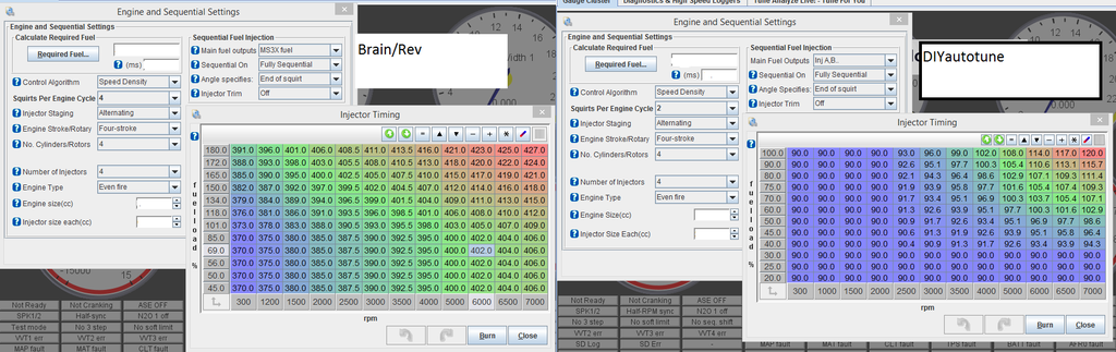
3) Look at the two tables below to illustrate the above. I've also seen base maps from rev where it's 360* across the board, and some that are similar to Brains.
Who is doing what and why?
(more to follow when I get onto a proper computer)
1) I know jack diddly squat about tuning this in MS, (aside from basic principle) and more so looking for collective direction and learning this together
2) I have seen/read enough input on this to drive a person mad. Mainly how conflicting the info is
3) Look at the two tables below to illustrate the above. I've also seen base maps from rev where it's 360* across the board, and some that are similar to Brains.
Who is doing what and why?
(more to follow when I get onto a proper computer)
Reply
 0
0

0


Junior Member
Joined: May 2015
Posts: 86
Total Cats: 11
Somebody please explain the philosophy of the maps posted above because they don't make any sense to me, especially for end of injection timing in units of btdc firing crank angle degrees.
Why would you end injection at low speed and load deep into the compression stroke? (90 degrees btdc)?
Why advance the end of injection with speed and load if you have fixed valve events (vvt is more complicated)?
Why would you end injection at low speed and load deep into the compression stroke? (90 degrees btdc)?
Why advance the end of injection with speed and load if you have fixed valve events (vvt is more complicated)?
Reply
0
0


This is a method I've read of for tuning injection timing OTR.
Dial in the VE table so that when logging and checking with MLV VE analyzer/TunerStudio VEAL there are no/barely any changes.
Blanket change the entire injector timing table + 20deg.
make no other changes and go for a long drive, hit all areas of the map. Either datalog it, or run TS VEAL, but make sure changes are NOT saved to the ECU.
Once the drive is done analyse the log in MLS/view the heatmap in TS VEAL. & make a record where in the map fuel would need to be removed & the injector timing used, (more efficient burn/therefore better injection timing).
Now move the timing table again - no other changes, you've not applied the suggested changes to the VE table.
Repeat the test. & make a note of suggested areas to remove fuel.
Keep repeating the test at different injector timing angles. Eventually you'll build a map of ideal injector timing angles for all areas of the map.
Once you have this map, apply it to the ECU, and then go out and re-tune the VE table.
Reply
0
0
Do you start with the whole table at 360*?
Somebody please explain the philosophy of the maps posted above because they don't make any sense to me, especially for end of injection timing in units of btdc firing crank angle degrees.
Why would you end injection at low speed and load deep into the compression stroke? (90 degrees btdc)?
Why advance the end of injection with speed and load if you have fixed valve events (vvt is more complicated)?
Why would you end injection at low speed and load deep into the compression stroke? (90 degrees btdc)?
Why advance the end of injection with speed and load if you have fixed valve events (vvt is more complicated)?
This is a method I've read of for tuning injection timing OTR.
Dial in the VE table so that when logging and checking with MLV VE analyzer/TunerStudio VEAL there are no/barely any changes.
Blanket change the entire injector timing table + 20deg.
do you start at 360* accross the board?
make no other changes and go for a long drive, hit all areas of the map. Either datalog it, or run TS VEAL, but make sure changes are NOT saved to the ECU.
Once the drive is done analyse the log in MLS/view the heatmap in TS VEAL. & make a record where in the map fuel would need to be removed & the injector timing used, (more efficient burn/therefore better injection timing).
you're losing me with the above: how would you know where fuel needs to be removed and injector timing used?
Now move the timing table again - no other changes, you've not applied the suggested changes to the VE table.
Repeat the test. & make a note of suggested areas to remove fuel.
I think I'm starting to understand now - you're basically saying what Sav already said. that is: keep adding injection timing everywhere that you see it fattening up the fueling. correct?
Keep repeating the test at different injector timing angles. Eventually you'll build a map of ideal injector timing angles for all areas of the map.
Once you have this map, apply it to the ECU, and then go out and re-tune the VE table.so you'll end up with a really rich table from the various places of increased injector timing, and you'll need to trim it, right?
Now onto a discussion I've dug up (though from 2011, so not sure how accurate):
https://www.miataturbo.net/megasquir...jection-55183/
Brains explanation:
here's what I use.

I might want to alter it slightly, this is based around the idea that you want to have all your fuel at the valve around 10� before the intake valve opens. So I'm using End-Of-Squirt.
NA intake valve opens 5�BTDC, so I have it at 375�. which is 10� before that. 360TDC + 5BTDC + 10 = 375.
I inject fuel another 10� sooner every 1000RPM or so, stopping at 5000RPM. I did this from reading through out the web as the accept "norm".
In boost I also inject the fuel even soon every few psi.
I didn't do extensive trial and error, but this map help reduce the over VE% by a few points throughout and seems to work well for me.
because he fails?
Here's how I understand it. The general rule of thumb is put the fuel 10* before your valve opens so you can 1. not only cool it off, but 2. the fuel has finished injecting and should be fully available for the intake stroke. So at idle I have my map set to putting the fuel at 10* before the valve opens. There should also be more vacuum at idle so it shouldn't take long for a short pulse width to get to the valve within the time it has from open to closed injector.
However, when you increase the rpms, the time from injector open to close reduces AND the pulse width increases. So I tell it to start injecting earlier. This was the fuel should still be hitting the valve JUST while compensating for the reduce milliseconds we are working within for the fuel to reach the intake valve.
I could be wrong, but this is how I understand it. I mean I realize we are squirting about 2-3" above the intake valve, so you could leave it at 375� throughout and call it a day, but I worry that even when set to end of timing, that you could still be injecting fuel too late on the cycle if you do it the way Vicoor is doing it.
I'll post the 3-D shapes soon, but it's important to look at the bigger picture. The numbers we settled on aren't that important unless you plan on building the exact same hardware setup. If that's the case, PM me and I'm happy to help.
The final VE map looks very similar to the one posted prior in terms of shaping. The slope through load was adjusted slightly, and also the curve shape after VE peak. This is where spending the time on a fixed-speed dyno and doing load sweeps at set RPM intervals is very helpful in pin-pointing exactly how your VE table is functioning, leaving O2 feedback and AE out of the equation is important, not trivial.
The full results of the Injection timing experiment I won't share at this point, as we discovered what appears to be a bug in the firmware, so the implementation is not as ideal as preferred. Basically, the MS3 has an issue when doing certain injection timing transitions. For now, we're running 300� BTDC for the entire map, which is not ideal for certain loads, but avoiding the firmware transition error is more important than sticking to ideals. In the end, the car has to drive perfect, so there are compromises you make to achieve that smoothness.
To elaborate further on the test itself, we chose 500 RPM intervals and held specific throttle angles, then swept injection timing and observed measured torque output. This isn't perfect as you also have to be mindful of MAP changes with torque output. At higher loads and RPMs, there was no change [WOT, for example], but at lower loads and RPMs, we were able to measure up to a 10% change in torque output at the same MAP, which is significantly more than we anticipated. Basically, an idealized injection timing map will improve lower load and RPM BSFC.
A few brief comments:
Only loading dynos actually measure torque. So you can't hold speed and load (sort-of, by throttle angle) and sweep parameters if you are using a basic dynojet, as they measure acceleration during transient pulls and back calculate torque and power.
The injection timing we are using is fixed end-of-injection, which can be set under the sequential fuel injection settings. That means the start of injection is constantly changing according to the duty cycle.
Remember that duty cycle = 720 crank angle degrees - injection duration in crank angle degrees. If I'm at 50% duty, my injection duration should be ~360 degrees, with start of injection back calculated from the end of injection time. That's assuming steady state operation with no X-tau etc (that stuff complicates it a lot). If I set a fixed value to an entire map, the injection timing is still changing all the time. If I have an EOI of 300 degrees BTDC firing and 20% duty, my duration is 144 degrees, so my SOI is 444 degrees BTDC.
300 deg btdc results in the injection event ending while the intake valve is still opening ("open valve injection"). You can sweep EOI earlier and later and see what happens. Without an emissions bench (to look at mixing according to HC ppm, CO%, and O2%) or combustion indication (to look at IMEP, combustion stability, etc), you can can only go on subjective assessement (did the engine run smoother at idle) or measured torque on a loading dyno.
Again, just trying to make sense of all of this.
One thing I want to clarify with everyone for the millionth (and last, I promise) time: we should all START with 360* accross the board on the injector timing table right? and advance/retard from there?
I ask because I'm having an OCD moment and want to completely re-do my ve table to perfection while eliminating this as a variable (I know, not really, but you know what I mean), then start "tuning" injector timing table from scratch.
My mistake (I think) thus far is just "going with" the injector timing table DIY provided in the base map, and not even really thinking about it til now, having tuned the rest of .... basically everything. (I'd also love it if DIYautotune chimed in here with their take on this. I'll PM them)
Reply
0
0

360� across the board would be the end-of-squirt at the same spot regardless of rpm. basically how MS2 does seq. injection.
my map was based on theory, math, other's maps, and a little bit of cruise tuning.
the idea is to have all the fuel at the ready just as the intake valve opens. since the injector opening, squirting, and closing time is calculated and you know the crank angle, you can tell the MS exactly when to squirt based on the crank.
but we know is takes MUCH less time to move from BDC to TDC when rotating at 1000RPM vs 7000RPM, so you start injecting sooner (based on those time calculations) so the fuel is always being injected at the most ideal time and not pooling on the intake valve or after the valve is already open, or closing and wasting fuel.
this is all about squeezing that last .1% of efficiency out of the motor.
this video helps illustrate:
the timing light is triggering at end-of-pulse with the injectors, watch where the injection happens relative to the "crank" when he starts moving the injection timing. That's ms2, so you only have a single value, no map.
then watch what happens when he revs, the injector fires at exactly the same time relative tot eh crank, but we know the motor is moving faster, but the injection should be getting longer with increases PWs.
as far as 360� vs. 90�:
360 is basically TDC. a number larger than that is earlier than TDC, so 450� would be 50� BDTC (9 o'clock). If you're using end-of pulse, then using 450� you'd be telling the MS to finish injecting fuel 50� before TDC.
I know the 90-93 intake cam opens 5� BTDC, so I used 375� as my idle zone number on my map. I padding by another 10� because the internet told me that you want to have fuel ready just about 10� before the valve starts to open.
I believe 90� is technically 450�. I'd have to look a crank rotation chart and MS code to confirm. It also depends on if you use end-of-pulse and begining-of-pulse, not sure what the DIY map uses.
You could also plug in -360� if you wanted, IIRC.
Last edited by Braineack; Jun 25, 2015 at 10:52 AM.
Reply
0
0
Junior Member
Joined: May 2015
Posts: 86
Total Cats: 11
Well here's an execise, on the topic of whether to start at 360 or some other number. Sit at idle and sweep injection timing and see where it starts to run like ****. You can make this as precise and scientific as you want or just take a quick stab at it. That's where Ryephile and I started. And let me tell you, the further you are from best combustion stability timing, the rougher it's going to run at a given wideband afr reading.
Reply
0
0
If you want to, doesn't really matter where you start if you gather date from the entire range.
That's why you log it and run the analyser in MLV, where it wants to pull fuel, the injector timing in this area is closer to ideal, where it wants to add it's worse than what was before.
you'll end up with a map in Excel/on paper of where the best injector timing is for each cell on the map based on the data gathering done previously.
Once you apply it to your ECU you'll need to retune
Once you apply it to your ECU you'll need to retune
Reply
1
1


Well here's an execise, on the topic of whether to start at 360 or some other number. Sit at idle and sweep injection timing and see where it starts to run like ****. You can make this as precise and scientific as you want or just take a quick stab at it. That's where Ryephile and I started. And let me tell you, the further you are from best combustion stability timing, the rougher it's going to run at a given wideband afr reading.
If you want to, doesn't really matter where you start if you gather date from the entire range.
That's why you log it and run the analyser in MLV, where it wants to pull fuel, the injector timing in this area is closer to ideal, where it wants to add it's worse than what was before.
you'll end up with a map in Excel/on paper of where the best injector timing is for each cell on the map based on the data gathering done previously.
Once you apply it to your ECU you'll need to retune
I'm sorry maybe I'm just misunderstanding, but it seems like you're being too vague. What is "best"? is "best" where it runs richest, like Sav is saying?
*EDIT: Ok having re-read your post for the 3rd time I think that's exactly what you're saying: pulling fuel, ie: rich = good. adding fuel, ie: lean = bad.
Reply
0
0
the idea is to reduce the amount of fuel needed to inject while maintaining the same AFR.
lets say you retard your entire map 20� and you're now richer. you can reduce your entire fuel table to lean back out.
that means you're able to inject less fuel to do the same thing as before, because you now have more efficient fueling--less waste.
lets say you retard your entire map 20� and you're now richer. you can reduce your entire fuel table to lean back out.
that means you're able to inject less fuel to do the same thing as before, because you now have more efficient fueling--less waste.
Reply
0
0

Yes, you want to do the sweeps with the same VE table. Then analyze all of the data, picking the best timing for each region.
To us with small injectors, there should be very little difference at high duty cycles, as injection will be occurring almost constantly.
Research I've done so far says that, even with larger injectors, timing is not as important at heavy loads / RPM's. I predict the most benefit of inj timing will be idle through cruise.
Reply
0
0

Junior Member
Joined: Mar 2012
Posts: 110
Total Cats: 13
Ive been trying to play with this using a scope connected to the cas and an injector. Not the easiest way to do things as im unsure of the exact cam timing and how to interpret the CAS signals. Ill post when i have a bit more luck...
Reply
0
0
I'm here to learn too.
But I will say the reason rich = good, is because it means if you make a change to your injector timing table and the AFR shows a richer reading, that means the combustion efficiency just improved, and you burned more of the available oxygen, thus less oxygen, and it reads richer. That's all I've got right now....
But I will say the reason rich = good, is because it means if you make a change to your injector timing table and the AFR shows a richer reading, that means the combustion efficiency just improved, and you burned more of the available oxygen, thus less oxygen, and it reads richer. That's all I've got right now....
Better injection timing = less fuel left in the port = more fuel in the chamber = richer AFRs for a given pulsewidth
Reply
1
1
I don't think altering the injection timing would alter the efficiency of the actual conflagration event. The injection timing doesn't alter the airflow or the timing of the actual event - all you're changing is when the fuel gets delivered to the intake charge. The AFRs read richer because you are getting more of the fuel delivered into the chamber, vs. leaving it on the walls of the port or the back of the intake valves.
Better injection timing = less fuel left in the port = more fuel in the chamber = richer AFRs for a given pulsewidth
Better injection timing = less fuel left in the port = more fuel in the chamber = richer AFRs for a given pulsewidth
Transients are a different topic, and I'm not talking about them.
Altering the timing absolutely changes the efficiency. A dyno will even show this.
Reply
0
0


