
ITT: MS3X VVT settings and tuning


From the tuning "guide":

It looks similar to the one I got loaded in mine, but if it have developed over time I dunno.
How it was created is another matter.
"The values preprogrammed to VVTuner were found to work well with a standard 2001-2005 Miata VVT motor after extensive research."
It looks similar to the one I got loaded in mine, but if it have developed over time I dunno.
How it was created is another matter.
"The values preprogrammed to VVTuner were found to work well with a standard 2001-2005 Miata VVT motor after extensive research."
It makes sense, coming in and out of various modes of the manifold. As a function of pressure, it seems we're ok, there are very few changes and they are smooth functions. But RPM leaves a lot to be desired.
On top of that, the graph stops kinda low. It *looks* like it's all done changing, but if/when I rev my motor to 8,500 or something, I wonder what will happen up there. It looks like there's a peak at 2000, and one at 3500, it would seem you'd expect another at 4000 (which you don't see), or maybe 7. And I've no idea if VICS will mess with this further.
Either way, more resolution will help. I'll try to whip up something which does a nice job of sub-sampling this down.
Reply
 0
0

0

Recently, we've fitted a VVT motor with a Flyin' Miata trigger wheel and had James put together some experimental code to decode the FM trigger with a Miata cam sensor. This is giving us more accurate data on what the cam is doing and we are using this to improve the VVT control. However, the final results of this development are still not out yet.
Are you guys looking at supporting this:
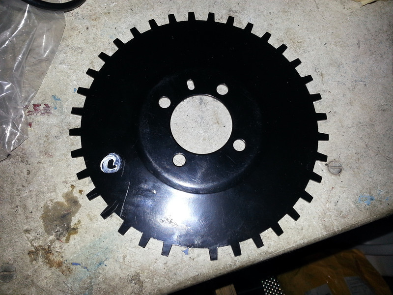
It's an OEM part, for the same motor in a different car. I was pretty excited to shoehorn it in as the teeth are much bigger, and with missing tooth and more of them it would have to help over the stock miata set up!
Also Matt - do you know what base-advance those are from? I.E. absolute numbers from TDC or some way to translate it to my MS3Pro?
Looking at DIY's number:
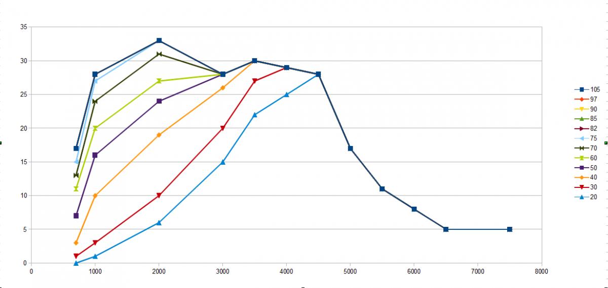
You can see a few things. Nothing changes above 6500, so there's no reason to keep that. I spend precious little time worrying about peak engine efficiency under 30 kpa since I'm only there on decel, so I dropped that row. Nothing changes over 85 kpa, so I axed that. It's linear from 5500-6500, and except for one pressure row (30, possible to mess with freeway cruise?) its also linear though the 4000 point, so I dropped that. Even where it isn't, it's 1/2 of a degree of timing error maximum, based on DIY's being gospel.
With those edits, the new chart looks like this:
Code:
DIY	700	1000	2000	3000	3500	4500	5500	6500
85	17	28	33	28	30	28	11	5
82	17	28	33	28	30	28	11	5
75	15	27	33	28	30	28	11	5
70	13	24	31	28	30	28	11	5
60	11	20	27	28	30	28	11	5
50	7	16	24	28	30	28	11	5
40	3	10	19	26	30	28	11	5
30	1	3	10	20	27	28	11	5
Reply
0
0
Glad to see that, I'm running 511 also. :-)
Which means... everyone's table should be offset by the min angle difference from their's to someone else's.
I did a super-quick, @ idle check and the numbers were bouncing so I only got 41 degrees of spread. I'll try again at higher rpm, I just wanted to see if the solenoid was working.
You're saying that the number is important, but you need it to be off? You find this number by holding some steady rpm then tweaking the test mode PWM up and down until you get it to stick somewhere in the middle?
We had our first VVT car running fine with someone elses base map. 2nd VVT engine we built wouldn't hold target at idle no matter what min/max or PID values we set. If you can get it to work with a hold duty value of zero and disabled, I'd like to know why I can't. There have been other functions in MS that have behaved that way. A value entered into a disabled function has an effect on the engine parameters. I seem to recall a clt temp fuel cut of about <160� being disabled on one of Williams cars cutting fuel anyway. I enabled it, set the clt temp to 250�, disable and voila, no spurious fuel cut. So as a habit now I look at the values in disabled functions when trouble shooting MS.
So to answer your question, yes. I enable, experiment with value to get a steady idle then disable.
I'd be curious to see one set you've used.
Like I said, I'll have to recheck mine. I got 269/310 - I really don't trust the 310 number.
I, too, am excited to see variation across boost levels, not sure the dyno access I'll get when I get it.
Since we don't have the ability to control the interpolation and don't really have enough RPM set points, choosing your set points for VVT is critical. On an N/A engine, I'm watching MAP very closely to determine where and how the engine is breathing to help determine RPM set points and values. Personally, I'd like a 16x16 or at least 8x16 table. Change the intake, porting, exhaust etc, and the VE changes so the RPM set points often need to change as well.
__________________


Reply
0
0

Joined: Jun 2005
Posts: 19,338
Total Cats: 574
From: Fake Virginia
Looking at DIY's number:
You can see a few things. Nothing changes above 6500, so there's no reason to keep that. I spend precious little time worrying about peak engine efficiency under 30 kpa since I'm only there on decel, so I dropped that row. Nothing changes over 85 kpa, so I axed that. It's linear from 5500-6500, and except for one pressure row (30, possible to mess with freeway cruise?) its also linear though the 4000 point, so I dropped that. Even where it isn't, it's 1/2 of a degree of timing error maximum, based on DIY's being gospel.
With those edits, the new chart looks like this:
This retains all of the important points in the graph, as best as I can tell, and should give you good street manners without loss of performance. Please let me know what you think!
You can see a few things. Nothing changes above 6500, so there's no reason to keep that. I spend precious little time worrying about peak engine efficiency under 30 kpa since I'm only there on decel, so I dropped that row. Nothing changes over 85 kpa, so I axed that. It's linear from 5500-6500, and except for one pressure row (30, possible to mess with freeway cruise?) its also linear though the 4000 point, so I dropped that. Even where it isn't, it's 1/2 of a degree of timing error maximum, based on DIY's being gospel.
With those edits, the new chart looks like this:
Code:
DIY	700	1000	2000	3000	3500	4500	5500	6500
85	17	28	33	28	30	28	11	5
82	17	28	33	28	30	28	11	5
75	15	27	33	28	30	28	11	5
70	13	24	31	28	30	28	11	5
60	11	20	27	28	30	28	11	5
50	7	16	24	28	30	28	11	5
40	3	10	19	26	30	28	11	5
30	1	3	10	20	27	28	11	5
I find your lack of units disturbing.
WELL WE PUT IN 30 AND GOT 75 BUT ONLY WHEN AT 3400. SO I PICKED UP A 40 AND THEN 3 LATER, I WAS EATING 100 AND SPAT OUT 2! I COULDN'T BELIEVE MY LUCK.
Reply
1
1
 I'm sure he's talking kpa vs rpm vs degrees
Yes but Y8S is an enguneer and they function best with precisely defined parameters. 
__________________
Reply
0
0

Supporting Vendor

Joined: Sep 2006
Posts: 2,332
Total Cats: 67
Correct. We're testing on an MS3-Pro based MSPNP (for '01-'05 cars) but it will apply to other MS3 variants as well.
Both MS3 and VVtuner table numbers are based on advance from the fully retarded position; they are relative rather than absolute.
Both MS3 and VVtuner table numbers are based on advance from the fully retarded position; they are relative rather than absolute.
Reply
0
0
One vote for at least 12 RPM set points like the VVTuner. For the turbo guys with power to spare it might not seem like a big deal. For us N/A tuners that can feel a little 5whp dip and see its effect on lap times in the data, it's significant. Ideally, ve and vvt tables have same rpm set points. Ive wrestled for many dyno pulls trying to get the interpolation of vvt tables to work with my ve tables for smooth afr plots. Throw big cams into the mix and its a real challenge.
Reply
0
0
Joined: Jun 2005
Posts: 19,338
Total Cats: 574
From: Fake Virginia
One vote for at least 12 RPM set points like the VVTuner. For the turbo guys with power to spare it might not seem like a big deal. For us N/A tuners that can feel a little 5whp dip and see its effect on lap times in the data, it's significant. Ideally, ve and vvt tables have same rpm set points. Ive wrestled for many dyno pulls trying to get the interpolation of vvt tables to work with my ve tables for smooth afr plots. Throw big cams into the mix and its a real challenge.
Also tell them you want a VVT-based fuel correction table so you can just tune your whole map at one cam angle and let the correction table fill in for varioius advances.
Reply
0
0
Already requested it as soon as we started this discussion. They seem open to it, at this point its a technical issue of if they can find the space for it in their roms and rams. :-)
When they do it, Emilio is going to buy me a cake. Thanks!
P.S. After getting those numbers in there, I had developed all these lean spots. Quite happy about that. :-) I wonder if I couldn't tune VVT just by varying it and picking the leanest conditions for a fixed RPM.
When they do it, Emilio is going to buy me a cake. Thanks!
P.S. After getting those numbers in there, I had developed all these lean spots. Quite happy about that. :-) I wonder if I couldn't tune VVT just by varying it and picking the leanest conditions for a fixed RPM.
Reply
0
0

But I need to get better control of my AFR signal to continue to do so since I now have reached my power goal on dyno (need to lock those top cells). Mid-range and transients still need attention.
AutoTune for VVT would not be impossible to imagine (at least easier help than now, it's pretty iterative and time consuming).
Reply
0
0
Thanks.
Reason I was making sure is because I'm basically using your table but with a bit of advance earlier (pre2500) and can't understand abe's suggested table or why vvt would only be effective up to 85kpa (unless that was for n/a cars only)
Reason I was making sure is because I'm basically using your table but with a bit of advance earlier (pre2500) and can't understand abe's suggested table or why vvt would only be effective up to 85kpa (unless that was for n/a cars only)
Reply
0
0
The suggestion is that the cam advance can be the same at manifold pressures above 85kpa (assuming that the extrapolation outside the table would be linear since the values for 82 and 85 are the same, it could read 450kpa instead and have the same effect, the same target value from 82kpa to infinity).
Reply
0
0
Exactly - from the looks of the graph, the dependence of optimum vvt phase diminishes with higher manifold pressures. Of course, the original data only covers from 85-100, so perhaps there's something interesting happening at twice the manifold pressure, but even just by eye, its pretty convincing. In short, spend more time on RPM than pressure.
Reply
0
0


