
Link to a high res photo of a V3.0 board?


Thread Starter
Junior Member
Joined: Dec 2006
Posts: 114
Total Cats: 1
From: NH
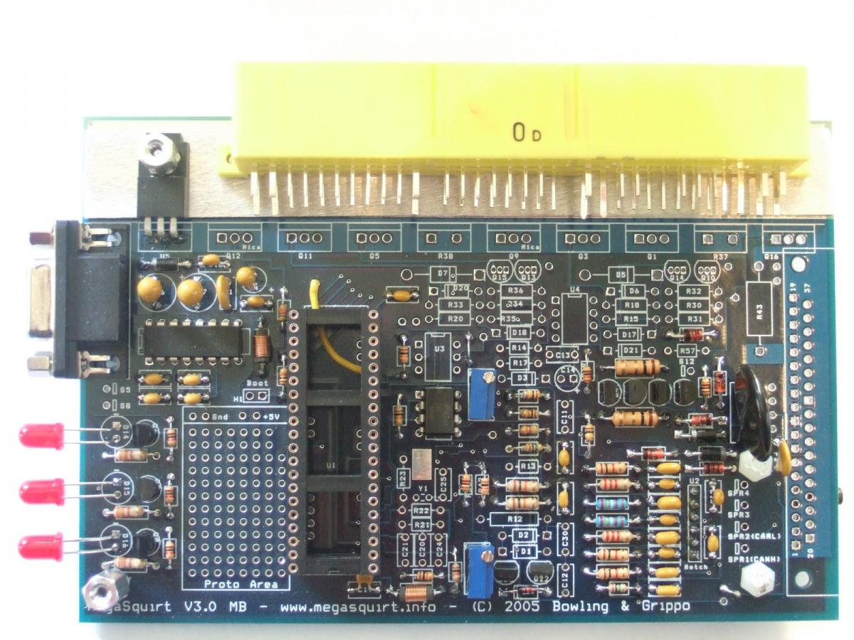
Anyone have a high res photo of a populated v3.0 board? Most of the photos I've found are lower resolution. I can't expand them enough to make sure I have the correct values.
I'm ******** a sync error problem. It could be I made an error populating the board. I'm not sure it is built 100% right. I get sync at some times and not others. (Both on vehicle and on the JimStim)
I'm ******** a sync error problem. It could be I made an error populating the board. I'm not sure it is built 100% right. I get sync at some times and not others. (Both on vehicle and on the JimStim)
Reply
 0
0

0


what does the composite log look like, can you post the screenshot?
are you using the ms3x board as the cam input?
Cause honestly, the VR input is like 1 jumper. I have plently of 3000px wide images, but none with the mods you would need to see.
are you using the ms3x board as the cam input?
Cause honestly, the VR input is like 1 jumper. I have plently of 3000px wide images, but none with the mods you would need to see.
Reply
0
0
Thread Starter
Junior Member
Joined: Dec 2006
Posts: 114
Total Cats: 1
From: NH
1. no sync error - kind of 'normal' probably need to advance the cam signal.
2. long cam then normal
3. long low cam signal
4. a wider cam signal
Haven't found any obviously hosed VR signals in this batch.
I need to go out and reinstall the MS3 and take a current look.
MS3X for CAM input, hall sensor, jumper for pullup installed.
I know about the VR jumper. Even I have a tough time messing that up. I was just wondering if you had a visual of the components in the VR circuit that I could check. Maybe I got a bad cap, or a wrong value resistor. The circuit behaves ok sometimes, but not at others. Both on vehicle, and on the JimStim.
Somehow I've got to get my brain reset so that I can figure this stuff out. Looks like I'm clutching at straws right now.
Reply
0
0

Senior Member
Joined: Nov 2007
Posts: 999
Total Cats: 73
From: Belgium
Not sure if it's any help, here's a pic of my board, prior to installing VR pullup
Here I added the pullup. I didn't place it in the proto area, it's much easier to install between left hole of R13 (=5V) and the right hole of R45 just below it. Result is the same (look at the schematics).
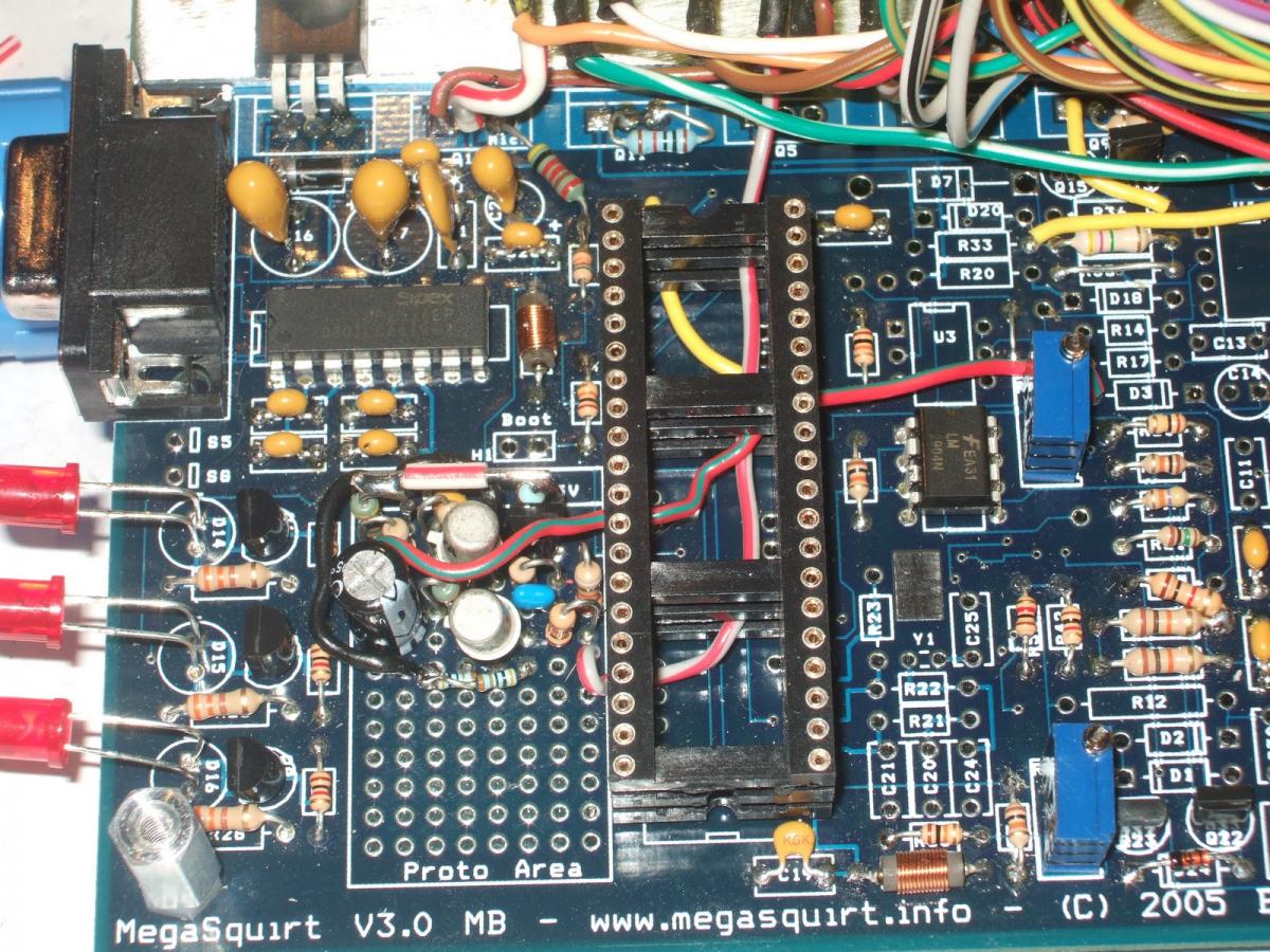
Here I added the pullup. I didn't place it in the proto area, it's much easier to install between left hole of R13 (=5V) and the right hole of R45 just below it. Result is the same (look at the schematics).
Last edited by WestfieldMX5; Nov 29, 2011 at 04:10 PM.
Reply
0
0

Thread
Thread Starter
Forum
Replies
Last Post
Zaphod
MEGAsquirt
47
Oct 26, 2018 11:00 PM
Frank_and_Beans
Supercharger Discussion
13
Sep 12, 2016 08:17 PM


