When you click on links to various merchants on this site and make a purchase, this can result in this site earning a commission. Affiliate programs and affiliations include, but are not limited to, the eBay Partner Network.
OK - Phew, ditching the Link Piggyback, going MS3 (bought new but second-hand) - feels great! Fab / wrenching isn't tough, it's the elec specifics / tuning that's got me scared!
(This is for a 2002 engine / wiring harness)
Done:
-Removed piggy-back injector signal wiring, reverted back to stock arrangement, removed FM intake mani w/ 4 additional injectors, etc, etc.
-GM IAT via threaded bung freshly mounted on engine-side end tank of intercooler, sensor installed in-place of OEM sensor using stock wiring
-Second threaded bung on engine-side end tank of intercooler - threaded nipple for signal > elec boost controller (bought via diyautotune)
-Sourced new boost signal to MS3 post-intercooler, pre-throttle
-Boost gauge signal sourced via nipple at rear / on top of intake mani
-Autometer wideband installed in downpipe, wired to gauge, then...
With that, all my engine-bay alterations are complete (I think?) - BUT there are a few things holding me back that I'd appreciate some help with in basic terms:
1A - Wideband
My Autometer wideband harness runs straight to the gauge - then I've got a +/- wires (2) that are meant to tag into the MS3 - I'm unsure where to tap these into on the PNP jumper harness - See photo - The PNP jumper harness has (5) wires that look to be meant to control the wideband (See Image 1, Image 2) - I just need to know where to tap my (2) signal wires from wideband > MS3.
I have the diagram from the manual I've found online (see link below) - but these (5) wires on my harness don't match the colors on the diagram - Help!
1B - Extra Wires?
Other than wideband signal, do I need to do anything else with these (5) wires on the harness? Can I just zip tie the unused ends out of the way? - Help!
2 - EBC
I picked up the diyautotune elec boost controller. Pluming is complete, needing to finish wiring. I know (from many, many threads about this topic) that one wire runs to switched +12v (probably going to tap the large White/Red wire on back of ECU plug - 4AFon the Miata Elec manual pic - See Image 3, Image 4) - it's the second wire I'm unsure where to tap at the MS3 PNP jumper harness (or should I tap into a wire on the OEM harness?) - Help!
https://trubokitty.com/#/installation
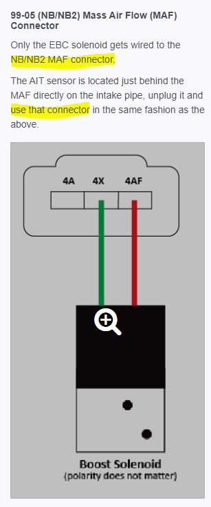
That's a link to Brain's guide for installing the ECU. His ecu's are configured to have the EBC and IAT wiring run through the factory MAF connector.
Wire the wideband as the autometer instructions indicate. Looks like the blue wire from the gauge should be going to the pink NB02 wire at the ecu. Blue/black should go to signal ground at the ecu. There are a couple. Check the pinout from the link and choose one to connect to.
Spartan - thanks so much for the links - I've run across them before, must have just gone over my head at the time.
OK - just to confirm:
IAT/EBC:
-Per Brain's link, looks like IAT gets wired in place of the stock IAT sensor - wires snipped, GM sensor tagged in with butt connectors - done
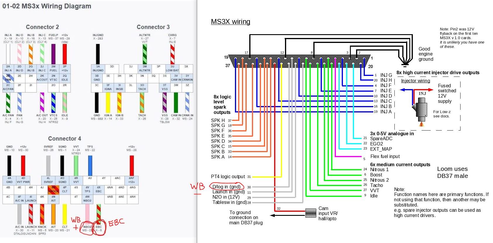
-The EBC gets wired to the oem MAF '4X' (signal) and '4AF' (12+) locations on the connector - which is also the same as the '4X / 4AF' pins on the oem ecu Connector 4 (circled in red, image below)
Wideband:
-Autometer Signal + wire gets connected at the '4W NB02' location on the oem ecu Connector 4 (circled in red, image below)
-Autometer Signal - wire gets connected to... um... the 'D/log in (gnd) 30' on the MS3x wiring harness? (circled in red, image below)
It's the only wideband I've ever seen require 2 connections to an ecu. Configuring might be odd as well since it's a 0-4V signal instead of 0-5V, and it has adjustable high and low points.


 0
0