When you click on links to various merchants on this site and make a purchase, this can result in this site earning a commission. Affiliate programs and affiliations include, but are not limited to, the eBay Partner Network.
MS3X Build with no RPM and doesnt read the crank sensor
So I bought MS3X with the expansion and decided to put it together with no knowledge of how the components work or even how to solder. However a friend of mine told me after he built it DIYPNP was the way to go and he taught me how to. I have since completed the mainboard and put it all together with a DIYBOB for my 00 SE miata. We were able to load the firmware and a tune on and see everything except the crank sensor output. The car wont sync and this is where we have been stuck for a few days. He is electronic savy so its not like I'm in this alone. We have been reading galore and have done all that we can without anyones help or thought.
So far we have gone through and made sure that the VR circuit is good and all the resitors are good. I have tuned all the POTS on both the daughterboard and the mainboard. I replaced R54 with a 100k resistor like I was instructed and have tuned R56 to 8.5 turns after going CCW 12+times. Also went 3.5 turns on the daughterboard for the cam sensor as well to make sure that wasn't the problem. We also ensured with a feeler guage today that the crank sensor is gapped to .35mm from the tooth. I am still on the stock wheel just FYI. Also I did go back and find that I missed a few pieces to complete the board that is in the pics and got those in place.
Today we actually changed out to his DIYPNP and we were able to get a crank signal when we had the noise filter turned on if that helps at all. The car still didn't run.
The question now is what else is there to check? I'm not sure what do now. I can post up a composite log when I get them sent to me but I don't know what else to do. Any help would be appericiated very much. And I am sure they you guys are getting tired of answering this question. Sorry for the long winded explination just wanted to give all the information that we have.
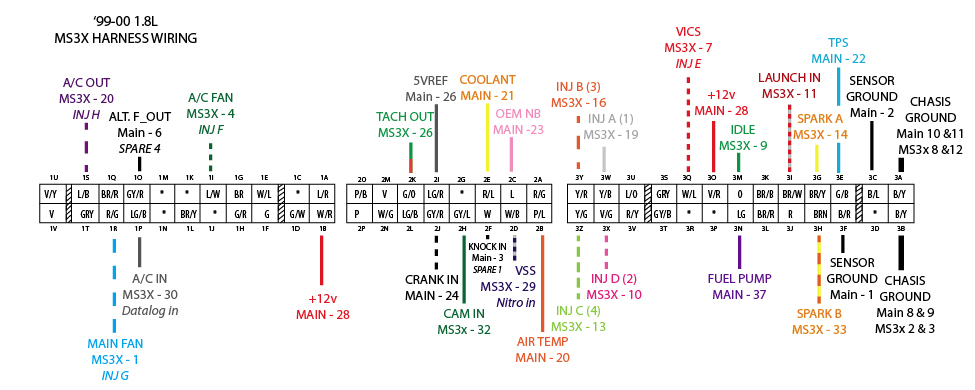
First thing i recommend is checking trubokitty.com .. Confirm your wiring is setup correctly per the writeup for the 99/00 . Did you do the complete build or the "just whats needed"?
That is what was used. We finished the BOB and even put a plug on the wideband. Its a few things more than what was on trubokitty because I didn't find that until the second night. So there are quite a few more resistors and diodes on the board than are needed. Double checked all the right ones were on and all are good.
If you have access to an oscilloscope you can probe different locations when cranking, and try to find where the signal is lost. This is easy mode. The other option will suck imo.
If you don't I would start by checking continuity of this whole circuit.
For example start by probing continuity between the crank sensor and tachIn. Then between tachIn and VRIN. Then between r45 and c31, then r45 and r46....and the list goes on.
Thanks guys for the help so far but we have checked for continuity on the entire VR circuit the other day before I posted and we cant find any. I might have to go get the tool to make it easy mode because we have to be missing something. Can it be the tune? We took a map off of DIYPNP site. Also we think it has something to do with the noise on the sensor due to what I mentioned in the first post. As for Q22, Q23 we put those in already and it didn't do anything. Any other suggestions?
Yes I tuned r56 CCW 12 times and then CW 8.5 turns. I also did the same things on the MS3 Daughterboard but 3.5 turns (for the cam). I can get a picture of the complete board when I get over to my buddies today. I put everything that you had on your site on the board plus some because I didn't find your site until a day into my assembly.


 0
0