MS3x Knock Module Settings Thread

 09-23-2012, 11:38 AM
#22

What input should we be using for the knock module on the MS3x for the incoming signal? I didn't build my MS3x, so I'm not sure how it is wired.
I want to make sure I don't pick a random input, then find out I have a conflict.
EDIT: Please confirm
I am just running the K1 wire from the knock module to a spare port on the DB37 so that I can use a connector on my DIYBOB which is where the wire from the knock sensor will connect.
I want to make sure I don't pick a random input, then find out I have a conflict.
EDIT: Please confirm
I am just running the K1 wire from the knock module to a spare port on the DB37 so that I can use a connector on my DIYBOB which is where the wire from the knock sensor will connect.
Last edited by miatauser884; 09-23-2012 at 01:33 PM.

Reply
 0
0

0
 09-24-2012, 11:02 AM
#24
Boost Czar


iTrader: (62)
Join Date: May 2005
Location: Chantilly, VA
Posts: 79,499
Total Cats: 4,080
you dont have anything on the LED outputs. So bring your knock sensor in one of the spare inputs and run it to K1 and done. Dont forget the wire on the daughterboard youll also have to add.
Reply
0
0
09-29-2012, 08:13 PM
#25
What spare inputs do I have? There was a wire from the knock module to the daughter board, then I ran k1 to a spare pin on the mainboard DB37, then connected the db37 pin to the knock sensor.
Here is the graph, but it doesn't look like y8s at all, so I think I must have done something wrong.
Here is the graph, but it doesn't look like y8s at all, so I think I must have done something wrong.
Reply
0
0
 09-30-2012, 06:15 PM
#29
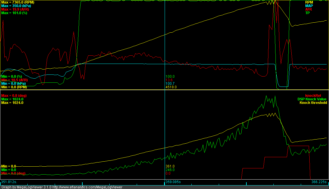
OK, it seems like I am getting a reasonable signal now. The hard part is determining which is knock that needs to be removed. The numerical value increases with rpm, but it is the difference in applitude at each new baseline that I am looking for. i.e. At idle I see about 10-20 as a normal value. Cruising at 3000rpm I see from 20-30 In boost the norm value seems to increase to 50 or more. If I see a value that is 25points higher then my perceived baseline at any point I will start to pull timing and see what happens.
Reply
0
0
09-30-2012, 07:07 PM
#31
I plotted knock, rpm, and map using MLV with map beign on the z axis. In just my shore run it appears to show a nice exponential curve as the rpm increases. I believe this exponential trend line could be used as the normal base line for referencing knock spike amplitude. Hence you can go with a rule that says you will retard knock for anyhng that is 25 points above baseline for a given rpm. I don't think it would be correct to just reduce spark anytime the value was above 25 points.
Here is my quick and dirty baseline. More testing will need to be performed to establish firm numbers.
idle: 15
2000: 18
3000: 20
3500: 30
4000: 38
4500: 50
5000: 70
Here is my quick and dirty baseline. More testing will need to be performed to establish firm numbers.
idle: 15
2000: 18
3000: 20
3500: 30
4000: 38
4500: 50
5000: 70
Reply
0
0
 10-01-2012, 09:51 AM
#34
What are you using as your knock determinate? 1.5x baseline, 2x baseline? I haven't quite figured it out.
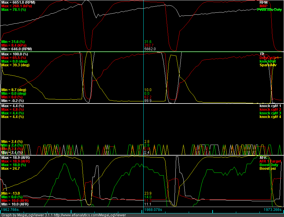
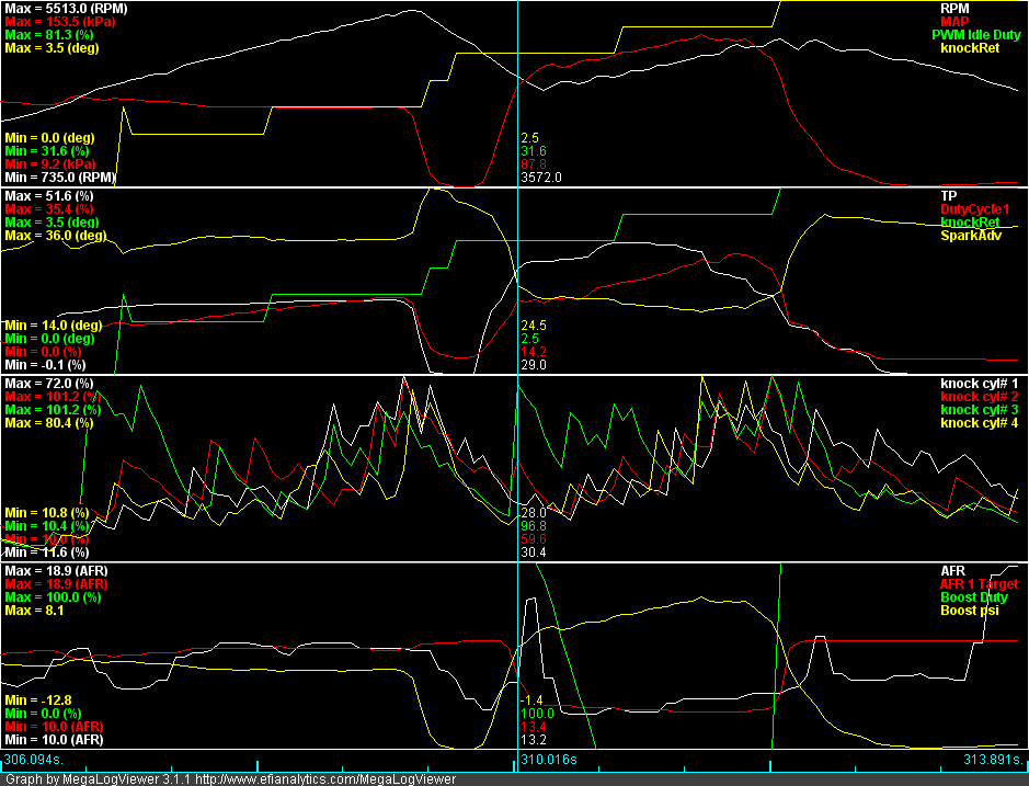
I do notice that cyl 3 seems to result in the largest spikes. I pulled some timing out of my map last night, but I'll have to wait until the weather clears up to test it.
Surprisingly I found quite a few spikes out of boost. 2500-4000rpm in the 50-90kpa range.
I pulled about .5 degrees if the spike was 25pts or more above baseline.
This might be helpful for visualizing baseline. I haven't tried it yet.
Re: feature request
by LT401Vette � Mon Oct 01, 2012 5:00 am
In MegaLogViewer you can create a custom field that will average over a set of records.
Custom Field Name: Averaged Knock
Formula: ([knock cyl# 1] + [knock cyl# 2] + [knock cyl# 3] + [knock cyl# 4]) / 4
Reply
0
0
10-01-2012, 10:29 AM
#35
2 Props,3 Dildos,& 1 Cat

Thread Starter
iTrader: (8)
Join Date: Jun 2005
Location: Fake Virginia
Posts: 19,338
Total Cats: 573
I get about 13-15 at idle on my knock graph
and 25-35 under boost at 4500
and up to 50 when boost is building and enrichments haven't caught up yet.
and 25-35 under boost at 4500
and up to 50 when boost is building and enrichments haven't caught up yet.
Reply
0
0
10-01-2012, 10:40 AM
#36
Elite Member
iTrader: (10)
Join Date: Jun 2006
Location: Athens, Greece
Posts: 5,979
Total Cats: 356
On my MS2, I have a "knock threshold" logged value. I put the "knock threshold" and the "DSP knock value" in the same MLV plot, and program the knock threshold settings so that the threshold is about 10-15% higher than the DSP knock value.
Reply
0
0
10-01-2012, 12:21 PM
#37
I've been playing with the scatter plots in MLV, and I think I'm able to see some useful data. I'm going to try to use the code above to plot the trendline along with the cylinder I see the most exaggerated knock spikes.
Maybe knock vs trendline vs rpm and knock vs trendline vs map
Reply
0
0