
MSIII v3.57 No CAS or CAM


Thread Starter
Junior Member
Joined: Apr 2010
Posts: 250
Total Cats: 125
From: Laguna Niguel
From what I can tell, I have no CAS or CAM signals. I have verified continuity on the wiring from the pins on the AMP connectors to the pins at the sensor connectors. I have verified 12v / ground at the sensor connectors. I have a fancier multimeter that is capable of measuring frequency / duty cycle, and have verified that the sensors are outputting something at the AMP connectors during cranking.
I have followed the instructions on setting the pull-up pots, and installed the resistor for the CAS pull-up.
This is a 2001+ VVT car.
I have followed the instructions on setting the pull-up pots, and installed the resistor for the CAS pull-up.
This is a 2001+ VVT car.
Reply
 0
0

0


If you followed the VR + pullup input, then input needs to be set to 'Falling Edge'.
Is the pull-up also installed on JP8 on the ms3x board? What size did you use on the mainboard?
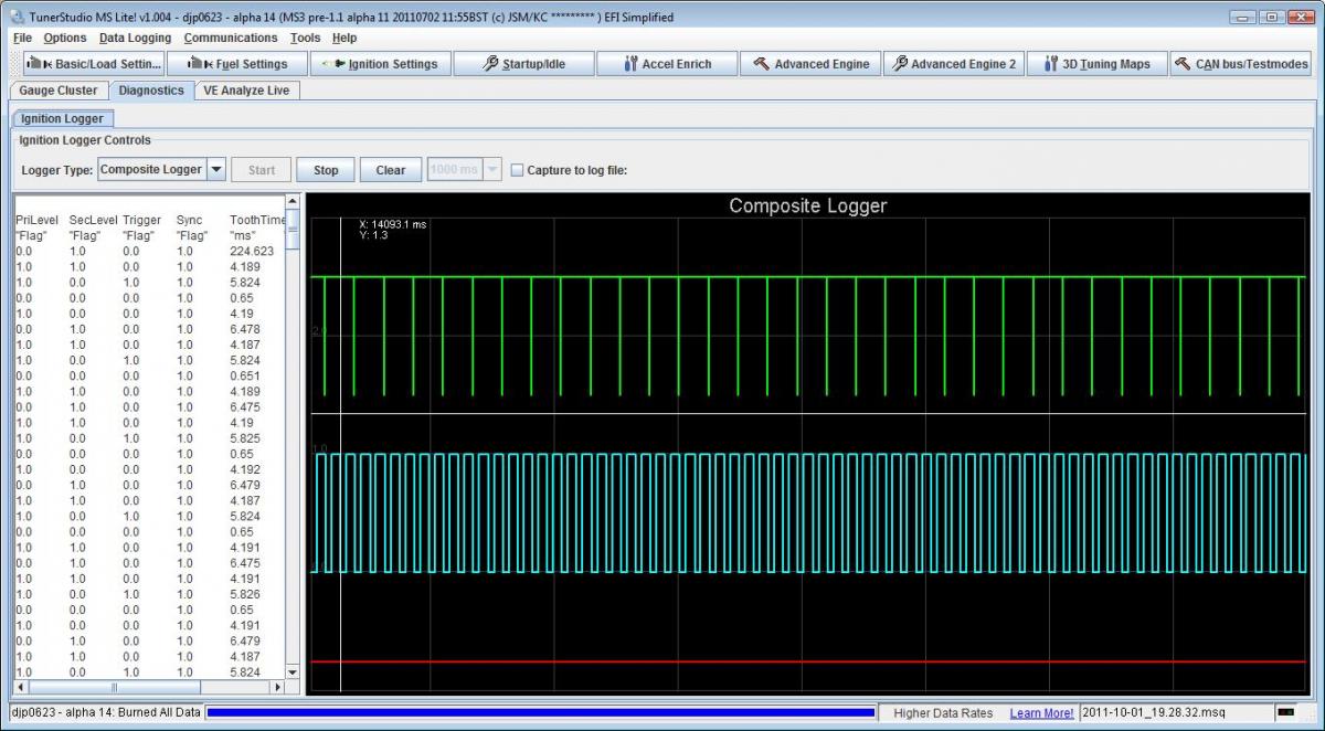
The best thing to do here is post a composite log during cranking so we can see if the MS is seeing the inputs correctly.
SIDENOTE: This MS has the alternator control circuit built in?
Is the pull-up also installed on JP8 on the ms3x board? What size did you use on the mainboard?
The best thing to do here is post a composite log during cranking so we can see if the MS is seeing the inputs correctly.
SIDENOTE: This MS has the alternator control circuit built in?
Reply
0
0
Thread Starter
Junior Member
Joined: Apr 2010
Posts: 250
Total Cats: 125
From: Laguna Niguel
I used a 470 ohm resistor. My logic (FWIW) is that the settings for the 99 from the DIYPNP would work with the sensor set. Hence the rising edge. J8 is jumpered.
Will get the composite log when I wake up a bit more.
Will get the composite log when I wake up a bit more.
Reply
0
0
Thread Starter
Junior Member
Joined: Apr 2010
Posts: 250
Total Cats: 125
From: Laguna Niguel
I just checked and find this:
Pin 24, MS3 Main connector is connected to the CAS center pin.
Pin 32, MS3X connector is connected the CAM center pin.
This appears to be correct per the manual.
Should I reverse them?
Is it possible to reverse the signals in the tune?
Pin 24, MS3 Main connector is connected to the CAS center pin.
Pin 32, MS3X connector is connected the CAM center pin.
This appears to be correct per the manual.
Should I reverse them?
Is it possible to reverse the signals in the tune?
Reply
0
0

Composite log is too short to be useful--can't see any patterns, or determine if there's signal there or just noise. Can you please capture a new log, cranking for 5 to 10 seconds?

Reply
0
0
Thread Starter
Junior Member
Joined: Apr 2010
Posts: 250
Total Cats: 125
From: Laguna Niguel
That composite logger was cranking for 10-15 seconds.
I found that I wired 12v to the crank position sensor instead of 5v. I have corrected it, but that did not fix the problem. Does the cam position sensor get 12v or 5v?
I have tried to do another composite logger and get nothing on it. Like it is getting no signal at all.
I am going to change the crank position sensor pull-up resistor to a 1k. Is there a similar pull-up resistor required for the cam position sensor?
Reply
0
0
01 wiring diagram shows crank sensor powered from the main relay (12V).
Reply
0
0
Thread Starter
Junior Member
Joined: Apr 2010
Posts: 250
Total Cats: 125
From: Laguna Niguel
The wiring diagram for the MS main connector has a note that a hall effect crank sensor needs a 5v supply. Now it looks like the cam sensor may also need 5v. Will rewire in a minute.
I reloaded the firmware and went to alpha 14 from 12.
I reloaded the firmware and went to alpha 14 from 12.
Reply
0
0
They get 12v. Are we doing this on a 2001 car or just a 2001 motor? Redoing the engine harness? what's going on?
Because I honestly dunno why the wiring is being touched...
Because I honestly dunno why the wiring is being touched...
Reply
0
0
Thread Starter
Junior Member
Joined: Apr 2010
Posts: 250
Total Cats: 125
From: Laguna Niguel
http://www.msextra.com/doc/ms3/hardware.html#wiring
In the main connector wiring diagram, between the pictorial representation of the crank sensor and the throttle position sensor, in small letters, "5v supply if hall sensor"
2001+ wiring harness
In the main connector wiring diagram, between the pictorial representation of the crank sensor and the throttle position sensor, in small letters, "5v supply if hall sensor"
2001+ wiring harness
Reply
0
0
Ground up build. Smartwire solid state switching (no fuses or relays), stripped down harness.
The rest of the sensors come up, other electrical systems good. Just the CMP,CKP issue so we're assuming it's a software config issue and not hardware or wiring. Sensors are outputting a signal when checked on a multimeter. Have not checked on an oscope yet but I'm pretty sure we'll see normal wave patterns. Will also try swapping sensors but they were known good sensors to begin with so no reason for them to die suddenly, and at the same time.
The rest of the sensors come up, other electrical systems good. Just the CMP,CKP issue so we're assuming it's a software config issue and not hardware or wiring. Sensors are outputting a signal when checked on a multimeter. Have not checked on an oscope yet but I'm pretty sure we'll see normal wave patterns. Will also try swapping sensors but they were known good sensors to begin with so no reason for them to die suddenly, and at the same time.
__________________


Reply
0
0
Thread Starter
Junior Member
Joined: Apr 2010
Posts: 250
Total Cats: 125
From: Laguna Niguel
Swapped them back to 12v
Since we have a running NB car waiting to be transformed, I pulled the sensor set out of it and installed it. Still no signals showing up in the composite logger.
We have a new MSIII coming tomorrow. Possibly an oscilloscope, too. Unless there is a problem in our tune settings, I am at a loss for what else to try.
Reply
0
0


