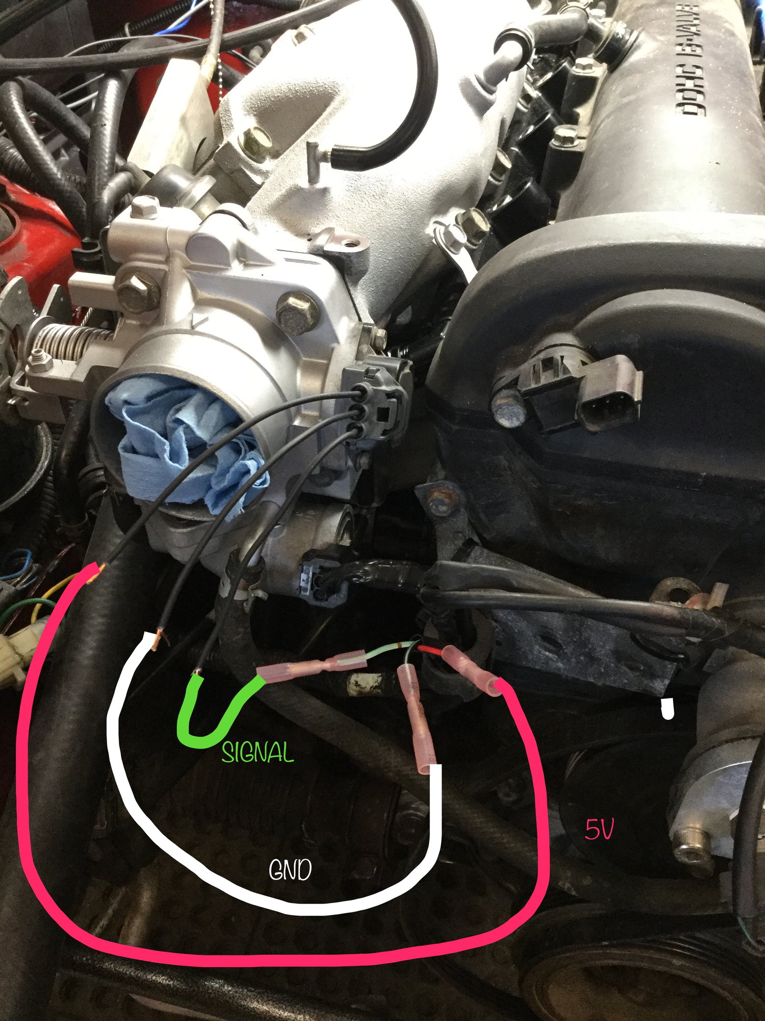
NB TPS on NA
#21
On the NA6, it's a little different because on the manual cars there is no 5v reference at the TPS connector. You need to add it yourself or have an ECU which passes 5v up one of the existing wires (such as an MSLabs MS3 Basic) and then wire the new NB connector properly.
On the NA8, it's as simple as changing the pigtail, since 5v is already there by default (and thus every aftermarket ECU worth owning also sends 5v there).
On the NA8, it's as simple as changing the pigtail, since 5v is already there by default (and thus every aftermarket ECU worth owning also sends 5v there).
am I getting warm?
#23
actually it turns out. On the MS PnP2
step 1. I enable J5 (that's the jumper for vTPS inside the ECU). which then sends that signal you talk about through red. ( thats with the NA6 harness manual version)
step 2 I just connect the 3 wires from the NA6 man. harness to the NB vTPS (NB8A 99)
step 3 check & calibrate TPS through tuner studios
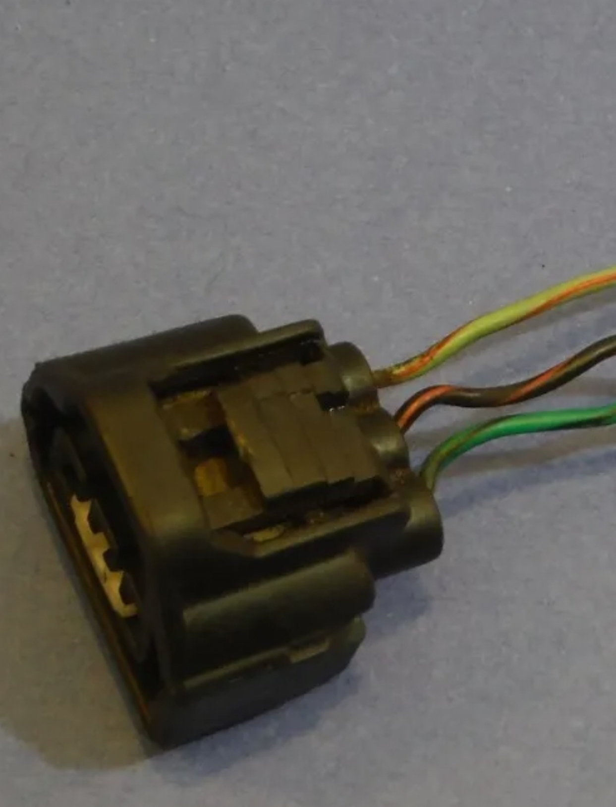
the thing which confused the hell out of me is the connector form the NB
I don't have one of those I just have a new one with a pig tail
in the case of he NA6 Manual version when looking at the TPS
top or TPS signal is Green white wire
middle is ground Black/ Green wire
bottom is 5v Ref red
will report back when it stops raining & confirm
#25
Stan, I have the same issue- '99 TPS with an aftermarket plug and no color referenced wires. I'm attaching it to a '95, 4 wire harness and I can't find a straight answer to the pinning on the '99 TPS which is frustrating as @#$% considering the number of these that have been done.
So what I uderstand from your post is that when looking at it, the top pin is the feed (light green/white), the middle is the ground (black/blue on mine), and the bottom is the 5v source (red/black on mine). Is this correct? As I understand it, the 4th red wire on my harness is not used since it performs some other function that is not needed (cuts A.C. at WOT or something to that effect).
So what I uderstand from your post is that when looking at it, the top pin is the feed (light green/white), the middle is the ground (black/blue on mine), and the bottom is the 5v source (red/black on mine). Is this correct? As I understand it, the 4th red wire on my harness is not used since it performs some other function that is not needed (cuts A.C. at WOT or something to that effect).
#26
Straight outta the Google box:
If you're not sure which connection on your TPS goes to which wire, check it with an ohmmeter/multimeter. Observe the resistance as the throttle opens and closes. Each pair of pins will behave differently:
If you're not sure which connection on your TPS goes to which wire, check it with an ohmmeter/multimeter. Observe the resistance as the throttle opens and closes. Each pair of pins will behave differently:
- The resistance between the 5 volt and ground pins will remain constant.
- The resistance between the ground and signal pins will be low with the throttle closed and high with the throttle wide open.
- The resistance between the 5 volt and signal pins will be high with the throttle closed and low with the throttle wide open.
#27
Yes, 6 combinations, but that's 5 more than what I'm looking for. So everyone has to go through the same *** pain every time someone does this? Why have a forum at all if self-discovery is the expectation for something that should be common knowledge at this point? That is what's frustrating.
Last edited by RocketJock; 06-13-2018 at 02:17 PM.
#28
3 pins, 3 wires, 9 combinations, but who's counting. So everyone has to go through the same *** pain every time someone does this? Why have a forum at all if self-discovery is the expectation for something that should be common knowledge at this point? That is what's frustrating.
And yes, since doing this should take you maybe 45 seconds with a multimeter, it does not fall into the "pain in the ***" category. There are many different TPS sensors. This is one of those classic "teach a man to fish" moments for you.
#32
Looking for tip how to wire in 3pin Mikuni TPS into NA with 4 pin 1.8. (Because of ITBs)
My car is miles away and I want to prepare connector and during swap I will just PNP everything.
My Mikuni have 5V ref, signal return and ground.
Miata have 4 wires, I was able to find wiring diagram but that just tells in which pin in ECU it goes to, I am used to diagrams which tells also what goes in each wire (ie. +5V, GND, signal, etc)
I know that:
RED - pin5
BLK/BLU - pin 11
LTGRN/WHT - pin 16
RED/BLK - pin 18
So basically I need pinout of 1.8 NA 94 which I am struggling to find.
#33
http://www.mellens.net/mazda/Mazda-M...994/wiring.pdf page 18.
edit - sorry, saw you had the diagram already
edit - sorry, saw you had the diagram already
#34
Looking for tip how to wire in 3pin Mikuni TPS into NA with 4 pin 1.8. (Because of ITBs)
My car is miles away and I want to prepare connector and during swap I will just PNP everything.
My Mikuni have 5V ref, signal return and ground.
Miata have 4 wires, I was able to find wiring diagram but that just tells in which pin in ECU it goes to, I am used to diagrams which tells also what goes in each wire (ie. +5V, GND, signal, etc)
I know that:
RED - pin5
BLK/BLU - pin 11
LTGRN/WHT - pin 16
RED/BLK - pin 18
So basically I need pinout of 1.8 NA 94 which I am struggling to find.
My car is miles away and I want to prepare connector and during swap I will just PNP everything.
My Mikuni have 5V ref, signal return and ground.
Miata have 4 wires, I was able to find wiring diagram but that just tells in which pin in ECU it goes to, I am used to diagrams which tells also what goes in each wire (ie. +5V, GND, signal, etc)
I know that:
RED - pin5
BLK/BLU - pin 11
LTGRN/WHT - pin 16
RED/BLK - pin 18
So basically I need pinout of 1.8 NA 94 which I am struggling to find.
https://www.miataturbo.net/engine-pe...athread-80469/
#36
Newb
Join Date: Dec 2016
Location: North of Shelburne Ontario, Canada on 100 acres
Posts: 34
Total Cats: 0
Not in my car, it’s been running like that for a few years. As the smart guys have pointed out earlier in the thread, it’s easy enough to check your car, there are three wires, only one will have a constant 5V with the ignition on.
Mine is.
“90 chassis 99 engine aftermarket pigtail + the evil hydra supplying the 5v”
Mine is.
“90 chassis 99 engine aftermarket pigtail + the evil hydra supplying the 5v”
Thread
Thread Starter
Forum
Replies
Last Post


