
Oochi's MS3X DIY Build


you gotta stop following the wikidot page, follow Frank's ms3x writeup. it's the only actual ms3x writeup out there. everything else is just confusing you.
the picture I posted a couple days ago is the only "mods" you need to do for your 90-93 install. just setting up the VR input jumpers for the crank signal input, and jumping the js9 to s12c for the 12v pullup to the daughterboard and expander. that's it. everything else you need is handled in the expander. fuel, spark, launch in, a/c in, a/c out, fan out, idle. so it's all just simply about making the harness.
I never really posted an ms3x writeup because it's so freaking simple I couldn't believe it, but I myself will refer back to franks page...it uses a lot of my pictures anyways

Reply
 0
0

0


Thread Starter
Junior Member
Joined: May 2011
Posts: 221
Total Cats: 1
From: Central Kentucky
Thank ya, I'm real good at over-thinking and confusing myself.
Is it OK to twist the grounds up like so and solder to 1 pin? Can I do this for the ms3x or should I run each individual wire out?
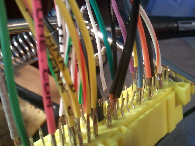
Also in that picture you can kind've tell how much smaller the white and black wire is. Those were the twisted and shielded ones but when unshielded they are a smaller gauge than the others and I want to make sure they are safe for running the cas on pin 2E and a sensor ground for the black. So cloooooose
Is it OK to twist the grounds up like so and solder to 1 pin? Can I do this for the ms3x or should I run each individual wire out?
Also in that picture you can kind've tell how much smaller the white and black wire is. Those were the twisted and shielded ones but when unshielded they are a smaller gauge than the others and I want to make sure they are safe for running the cas on pin 2E and a sensor ground for the black. So cloooooose
Reply
0
0
it's fine.
but are you using heat shrink on the wires once you're done?
One idle mod i do suggest is this:
I just tested the unit i built last week and the idle range sucks. On my car it's between 20-60% PWM where 20% is about 750rpm and 60% is closer to 3K. (I have the idle mod built onto my mainboard)
With the expander unmodified I had to use a range of 70-90% and the step increases per % were huge and maybe idle tough on my car even when using timing correction code. I'm about to modify this board now for it.
im considering doing the same to boost control out as well.
but are you using heat shrink on the wires once you're done?
One idle mod i do suggest is this:
MS3X Idle circuit modification
It’s optional but strongly adviced to install a flyback diode over the idle valve. Without it, the idle pwm % will be around 70, whereas you want it to be around 30 for best control.
Install a 1N4001 with the banded side to 12V and the other side to the idle output of the MS3X (pin 9). I soldered it directly on the Tyco connector.
With the expander unmodified I had to use a range of 70-90% and the step increases per % were huge and maybe idle tough on my car even when using timing correction code. I'm about to modify this board now for it.
im considering doing the same to boost control out as well.
Last edited by Braineack; May 19, 2012 at 11:32 AM.
Reply
0
0
yeah went ahead and did it for idle and boost:
the trace on r64 is very fragile, so i went ahead and dumped hot glue all over it to support the wire and make sure it wouldn't pull up. I'd suggest doing this into your harness...
the trace on r64 is very fragile, so i went ahead and dumped hot glue all over it to support the wire and make sure it wouldn't pull up. I'd suggest doing this into your harness...
Last edited by Braineack; May 22, 2012 at 05:43 PM.
Reply
0
0
Thread Starter
Junior Member
Joined: May 2011
Posts: 221
Total Cats: 1
From: Central Kentucky
it's fine.
but are you using heat shrink on the wires once you're done?
One idle mod i do suggest is this:
I just tested the unit i built last week and the idle range sucks. On my car it's between 20-60% PWM where 20% is about 750rpm and 60% is closer to 3K. (I have the idle mod built onto my mainboard)
With the expander unmodified I had to use a range of 70-90% and the step increases per % were huge and maybe idle tough on my car even when using timing correction code. I'm about to modify this board now for it.
im considering doing the same to boost control out as well.
but are you using heat shrink on the wires once you're done?
One idle mod i do suggest is this:
I just tested the unit i built last week and the idle range sucks. On my car it's between 20-60% PWM where 20% is about 750rpm and 60% is closer to 3K. (I have the idle mod built onto my mainboard)
With the expander unmodified I had to use a range of 70-90% and the step increases per % were huge and maybe idle tough on my car even when using timing correction code. I'm about to modify this board now for it.
im considering doing the same to boost control out as well.
Reply
0
0
up to you. the MS developers would say going to the spot i did isn't best and you shoudl go back directly to 12v, so doing it in your harness like Frank suggests in his writeup is probably the best way.
here's my ms3x that I built, tested today running flawlessly:


here's my ms3x that I built, tested today running flawlessly:
Reply
0
0
Thread Starter
Junior Member
Joined: May 2011
Posts: 221
Total Cats: 1
From: Central Kentucky
the black case looks really good. What year is the one you made for? It appears that I have INJ A and B switched on my harness. So does INJ A go to Pin 2v which is injectors 2 & 4? Where do you have your ms3x grounds going to?
The idle mod isn't on the 90-93 write up but is on the 99. But it would be the same anyway?
The idle mod isn't on the 90-93 write up but is on the 99. But it would be the same anyway?
Reply
0
0

Elite Member
Joined: Mar 2006
Posts: 1,574
Total Cats: 106
From: Schwarzenberg, Germany
As I also have some problems getting the boost control to work correct with the MS3x - could I also try to put the diode on the connector of the solenoid?
Reply
0
0
the black case looks really good. What year is the one you made for? It appears that I have INJ A and B switched on my harness. So does INJ A go to Pin 2v which is injectors 2 & 4? Where do you have your ms3x grounds going to?
The idle mod isn't on the 90-93 write up but is on the 99. But it would be the same anyway?
The idle mod isn't on the 90-93 write up but is on the 99. But it would be the same anyway?
Yes, I'd still do the idle flyback mod on the 90-93 install, I did not like the function on the idle valve without it (testing the diode today) compared to how my personal ms3x runs on my car.
http://msextra.com/forums/viewtopic.php?f=125&t=41437
Reply
0
0
Thread Starter
Junior Member
Joined: May 2011
Posts: 221
Total Cats: 1
From: Central Kentucky
Ok I suppose I need to switch my injector outputs. Where are your ms3x grounds going? I'm also having trouble finding crimp pins for my middle connector. Which ones do I need and where can I find them? Radioshack only had circle ones, couldnt find any anywhere else.
Reply
0
0
Buy them online they are tyco parts the part numbers are in my writeup...I do really like franks solution but im too used to making the harnesses...they are like second nature to me now but I still love the diybob the best
I already said how I ran those grounds.
I already said how I ran those grounds.
Reply
0
0
i pulled the diodes, i burnt up c16. running a jumper from s12 with inline diode to the back of d5. Much have been too much flyback through the s12c jumper and killed things.
Reply
0
0
Thread Starter
Junior Member
Joined: May 2011
Posts: 221
Total Cats: 1
From: Central Kentucky
Will I have to change much using your .msq if I'm running a bone stock 1.6 that wont be on seq fuel/spark?
I've also followed this: http://www.msextra.com/doc/ms3/firmware.html which I loaded the firmware and had success with the stim, except for tach.
Edit: When trying to open your tune on my laptop, I get an window that says
I've also followed this: http://www.msextra.com/doc/ms3/firmware.html which I loaded the firmware and had success with the stim, except for tach.
Edit: When trying to open your tune on my laptop, I get an window that says
Signatures do not match!
Tune file signature: MS3 Format 0235.001
Configuration signature: MS3 Format 0095.005
Tune file signature: MS3 Format 0235.001
Configuration signature: MS3 Format 0095.005
Last edited by Oochi; May 24, 2012 at 01:22 AM.
Reply
0
0
im using pre1.1beta21. ...looks like youre on very old firmware.
I'd load the beta21 if I weres you.
You should also get on the latest TS beta, as it will download firmwares for you if you dont alreayd have them on your laptop.
youll have to change your req_fuel, change from fully seq to semi-seq in engine constant, change from COP spark to wasted spark, change the dwell from 2.1 to like 3.5 or whatever, change all the inputs and outputs like launch, boost, idle control, fans etc etc to make sure they all jive with your MS and what circuits they are on, and then it would probably start up and run just fine.
You'll have to tweak the PID idle settings and the VE ilde table to fine tune the fuel, but it will be a great start otherwise.
Reply
0
0
Thread Starter
Junior Member
Joined: May 2011
Posts: 221
Total Cats: 1
From: Central Kentucky
youll have to change your req_fuel, change from fully seq to semi-seq in engine constant, change from COP spark to wasted spark, change the dwell from 2.1 to like 3.5 or whatever, change all the inputs and outputs like launch, boost, idle control, fans etc etc to make sure they all jive with your MS and what circuits they are on, and then it would probably start up and run just fine.
You'll have to tweak the PID idle settings and the VE ilde table to fine tune the fuel, but it will be a great start otherwise.
You'll have to tweak the PID idle settings and the VE ilde table to fine tune the fuel, but it will be a great start otherwise.
Reply
0
0
BTW, just tested the unit and adding the diode for idle output to s12 is good. Dropped the functional range from 70-90% PWM to 20-60% PWM...which is idnetical to my unit. idling great even on wasted spark and batch injection.
beta firmware: http://msextra.com/forums/viewtopic.php?f=125&t=44957
beta firmware: http://msextra.com/forums/viewtopic.php?f=125&t=44957
Reply
0
0


