
Parts needed to upgrade MS1 to MS3x?


Thread Starter
Elite Member
iTrader: (24)
Joined: Jul 2007
Posts: 3,759
Total Cats: 35
From: Cypress, TX
I'm about to pull the trigger on everything I need for MS3x. Current setup is a Brainy built piggyback 90-93 MS1 with boost control and a fan control added. I will be going full standalone with MS3x. I can add in the wires to the Xdb37 myself.
I need all of this, right?
1 x DB37 solder cup connector for MS3X
1 x MegaSquirt-III daughterboard kit
1 x MegaSquirt-III MS3X Expansion Card
1 x MegaSquirt-III V3.0 Black Anodized Case
Anything else? What about the screws for fastening the MS3 daughtercard down shown here?
My setup will be a VVT head and NB sensors with LS2 truck coils running full sequential in my 92.
built piggyback 90-93 MS1 with boost control and a fan control added. I will be going full standalone with MS3x. I can add in the wires to the Xdb37 myself.I need all of this, right?
1 x DB37 solder cup connector for MS3X
1 x MegaSquirt-III daughterboard kit
1 x MegaSquirt-III MS3X Expansion Card
1 x MegaSquirt-III V3.0 Black Anodized Case
Anything else? What about the screws for fastening the MS3 daughtercard down shown here?
My setup will be a VVT head and NB sensors with LS2 truck coils running full sequential in my 92.
Last edited by Bryce; Mar 7, 2012 at 05:06 AM.
Reply
 0
0

0


looks like you got it. all you'd need to do to make it standalone is add the idle valve output out the db37 of the ms3x so it's running idle control into your current harness. then just keep the stock ecu off the harness.
Reply
1
1

I'm about to pull the trigger on everything I need for MS3x. Current setup is a Brainybuilt piggyback 90-93 MS1 with boost control and a fan control added. I will be going full standalone with MS3x. I can add in the wires to the Xdb37 myself.
I need all of this, right?
1 x DB37 solder cup connector for MS3X
1 x MegaSquirt-III daughterboard kit
1 x MegaSquirt-III MS3X Expansion Card
1 x MegaSquirt-III V3.0 Black Anodized Case
Anything else? What about the screws for fastening the MS3 daughtercard down shown here?
built piggyback 90-93 MS1 with boost control and a fan control added. I will be going full standalone with MS3x. I can add in the wires to the Xdb37 myself.I need all of this, right?
1 x DB37 solder cup connector for MS3X
1 x MegaSquirt-III daughterboard kit
1 x MegaSquirt-III MS3X Expansion Card
1 x MegaSquirt-III V3.0 Black Anodized Case
Anything else? What about the screws for fastening the MS3 daughtercard down shown here?
The screws are included with the MS3 daughterboard kit.

Reply
1
1
Thread Starter
Elite Member
iTrader: (24)
Joined: Jul 2007
Posts: 3,759
Total Cats: 35
From: Cypress, TX
I hope this can become an conclusive thread for those wishing to upgrade to MS3/MS3X.
I shall be using the following directions, but have a question and possibly a correction for them.
1: If I do the mods below, pop in the ms3 card, fiddle with the software some, it should work in my stock batch-firing configuration with the stock CAS, right?
2: And then if I wire the NB crank and cam sensors to the CAS plug and change the timing settings? I read that the NB CKP and CMP outputs are electrically identical to the CAS outputs, besides the number of teeth.
When I say work, I mean fuel and spark. Obviously my IAC isn't going to work if I don't have provisions for it on the mainboard(Thats what the expander card will be there for ).
).
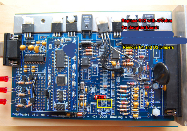
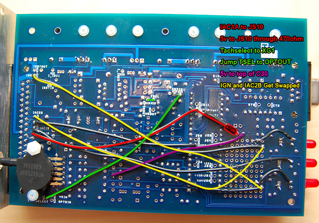
3: In the second picture, I need to remove the jumper from tachselect to optoin? (Its not jumpered in the picture, but it is on my board) I'm thinking this was an implicit step.
4: Do I also need to connect S12C and JS9 to get 12V to the daughtercard? According to the MS3 build step 23 (http://msextra.com/doc/ms3/build_manual.html), I do.
More questions later.
I shall be using the following directions, but have a question and possibly a correction for them.
1: If I do the mods below, pop in the ms3 card, fiddle with the software some, it should work in my stock batch-firing configuration with the stock CAS, right?
2: And then if I wire the NB crank and cam sensors to the CAS plug and change the timing settings? I read that the NB CKP and CMP outputs are electrically identical to the CAS outputs, besides the number of teeth.
When I say work, I mean fuel and spark. Obviously my IAC isn't going to work if I don't have provisions for it on the mainboard(Thats what the expander card will be there for
).3: In the second picture, I need to remove the jumper from tachselect to optoin? (Its not jumpered in the picture, but it is on my board) I'm thinking this was an implicit step.
4: Do I also need to connect S12C and JS9 to get 12V to the daughtercard? According to the MS3 build step 23 (http://msextra.com/doc/ms3/build_manual.html), I do.
More questions later.
Reply
0
0
1. yes. Do those mods and you can run the ms3x and run spark/fuel (and everything else) through current the mainboard outputs.
2. It should tehcincally work, but you'd want to bring the cmk signal into the MS3x cam in input--it's a much better input.
Then it's important the polarity of the signals are both the same, where you might have to move the green wire stuff back to how it was for MSI (tachselect to optoin, xg1 to xg2, and jump d1 and d2 again).
I really can't remember which method is the correct polarity to match the cam in through the ms3x card...you'll easily figure it out when you run the composite logger.
In both cases, you'd remove the red and purple wires seen above, that's replaced my the ms3x input.
And r12 doesnt really need to be changed at all, it can stay the 390ohm that was supplied regardless.
Best case, you'd use the VR w/pullup input for the ckp signal instead of the opto circuit if you have it populated.
3. yes, it goes to xg1 now instead.
4. yes, this allows anything on the js0-js4 to work and gives the ms3x card it's pull-ups to 12v.
Reply
0
0
Thread Starter
Elite Member
iTrader: (24)
Joined: Jul 2007
Posts: 3,759
Total Cats: 35
From: Cypress, TX
Edit: Made a new thread for the sync error here:
https://www.miataturbo.net/showthrea...623#post848623
https://www.miataturbo.net/showthrea...623#post848623
Last edited by Bryce; Mar 15, 2012 at 01:05 PM.
Reply
0
0

Thread
Thread Starter
Forum
Replies
Last Post
graexodus
Miata parts for sale/trade
9
Oct 25, 2015 03:34 PM


