
She squirted in my eye


hmmm. i misread you board, that seems to be for the a/c idle up in the software.
It's the stupid naming convention. This is one thing I've yelled at Ken/James about.
On the mainboard i/os are labeled JS0-11, but on in the software, they dont match up at all.
For example, pa0 = js11.
This screws me up everytime as I dont have them memorized.
It's the stupid naming convention. This is one thing I've yelled at Ken/James about.
On the mainboard i/os are labeled JS0-11, but on in the software, they dont match up at all.
For example, pa0 = js11.
This screws me up everytime as I dont have them memorized.
Last edited by Braineack; Sep 5, 2012 at 08:33 AM.
Reply
 0
0

0
To be perfectly honest, as I'm going over it right now, everything looks good based on the msq.
I know I mapped this out, i just need to find the spreadsheet in which I setup your unit, just havent had time to jump on my PC at home.
But as I'm looking right now I see:
Tachout - JS4 - Spare 4
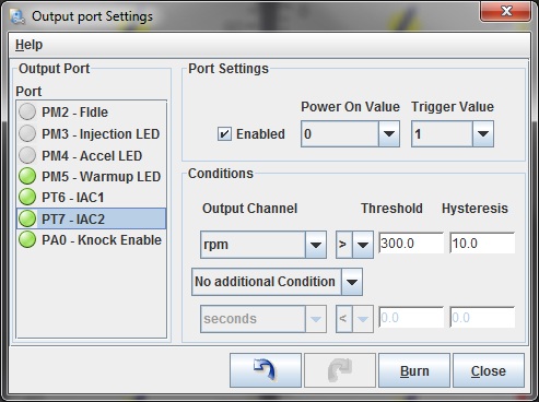
A/C Out - JS11/PA0 - Spare 3
A/C IN - JS7/PE0 - Spare 2
Boost - JS2/IAC2 - Spare 1
VICS - JS0/IAC1 - Out Side of Case
Knock IN - JS5/AD6 - Out Side of Case
Spark B - D14/PM4 - IAC2B
Launch - PIN15/PE1 - IAC2A
Fan - D15/PM5 - IAC1B
Cam in - JS10 - IAC1A
Spark A - D13/PM3 - IGN
Which leaves us with the trigger for the alternator controller... It doesn't seem like I built it. I know I tested it on the bench, so I probably did something dumb and moved outputs around.
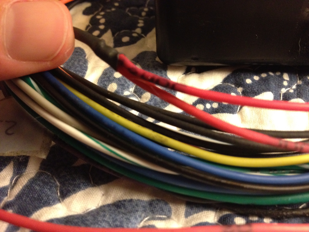
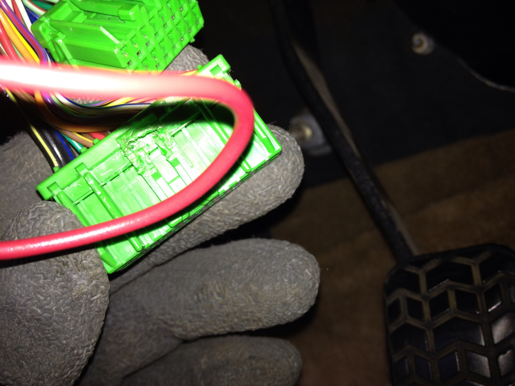
Red, can you do me a favor and figure out where the three wires going into the black box go. The pink is the output back to the harness to 1O or 1C (cant remember off head), and the red should be 12v, and one of the blacks should go to ground. I need to find out exactly where the other black wire goes to figure out what the hell I did here.
I obviously ran in back to the ECU, so I gotta figure out where and what's activating it, as everything is pretty much spoken for right now. But you do have to option of bypassing the RPM trigger, you'd have to cut out that pink wire from inside hte black box and splice it to one of those two black jumper wires you see inside.
Get back to me on that black wire and lets see if we can solve this today.
I know I mapped this out, i just need to find the spreadsheet in which I setup your unit, just havent had time to jump on my PC at home.
But as I'm looking right now I see:
Tachout - JS4 - Spare 4
A/C Out - JS11/PA0 - Spare 3
A/C IN - JS7/PE0 - Spare 2
Boost - JS2/IAC2 - Spare 1
VICS - JS0/IAC1 - Out Side of Case
Knock IN - JS5/AD6 - Out Side of Case
Spark B - D14/PM4 - IAC2B
Launch - PIN15/PE1 - IAC2A
Fan - D15/PM5 - IAC1B
Cam in - JS10 - IAC1A
Spark A - D13/PM3 - IGN
Which leaves us with the trigger for the alternator controller... It doesn't seem like I built it. I know I tested it on the bench, so I probably did something dumb and moved outputs around.
Red, can you do me a favor and figure out where the three wires going into the black box go. The pink is the output back to the harness to 1O or 1C (cant remember off head), and the red should be 12v, and one of the blacks should go to ground. I need to find out exactly where the other black wire goes to figure out what the hell I did here.
I obviously ran in back to the ECU, so I gotta figure out where and what's activating it, as everything is pretty much spoken for right now. But you do have to option of bypassing the RPM trigger, you'd have to cut out that pink wire from inside hte black box and splice it to one of those two black jumper wires you see inside.
Get back to me on that black wire and lets see if we can solve this today.
Reply
0
0
okay that helps, thanks. that's spare 1. let me see what the heck i did.
AH, I see. I used a tip120 for the trigger. I thought that was the boost control driver, but you don't have that on your board; I think that's what we sacrificed to do everything you wanted--and probably tripped me up when doing the basemap.
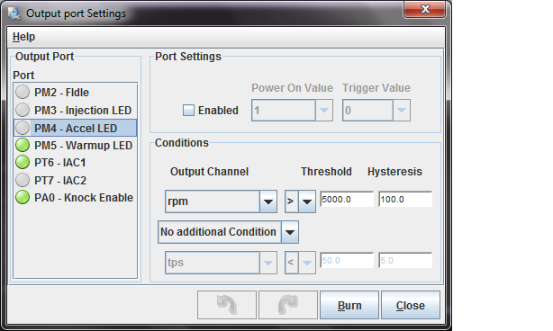
okay, do this and report back (turn boost control to off if it's set to on):
AH, I see. I used a tip120 for the trigger. I thought that was the boost control driver, but you don't have that on your board; I think that's what we sacrificed to do everything you wanted--and probably tripped me up when doing the basemap.
okay, do this and report back (turn boost control to off if it's set to on):
Reply
0
0

Thread Starter
Senior Member
iTrader: (14)
Joined: Oct 2006
Posts: 677
Total Cats: 6
From: South East Florida
Thanks brain. Will be testing next weekend.
What are your thoughts on my other issue? See post #8.
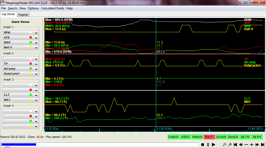
I logged that wired diagnostic thing, but have no idea how to read it.
Why is it idling so crummy? Is this tied to why I had to add so much fuel? I believe the req fuel is set properly (11.something).
What are your thoughts on my other issue? See post #8.
I logged that wired diagnostic thing, but have no idea how to read it.
Why is it idling so crummy? Is this tied to why I had to add so much fuel? I believe the req fuel is set properly (11.something).
Reply
0
0
depends on a lot of things, but yes, low volts will cause oddness as the ECU compensates for voltages in some enrichments.
is it only rough at idle? does it feel like it's only running on 2-cly or something?
is it only rough at idle? does it feel like it's only running on 2-cly or something?
Reply
0
0
Thread Starter
Senior Member
iTrader: (14)
Joined: Oct 2006
Posts: 677
Total Cats: 6
From: South East Florida
Not just idle. Yes, feels like it is only running on 2 or 3 cylinders. Clos561 thought the same.
Timing light flashed when I put it on each spark plug wire.
Is it possible that only two of the injectors are firing? <stupid question
This is from the last log I took. Pretty sure I had a spare battery jumping at the time. Volts around 11.
Timing light flashed when I put it on each spark plug wire.
Is it possible that only two of the injectors are firing? <stupid question
This is from the last log I took. Pretty sure I had a spare battery jumping at the time. Volts around 11.
Reply
0
0
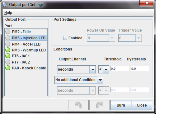
PW3 and PW4, on logs. Pulse Width. But it seems you didnt turn on PT7 like I said to.
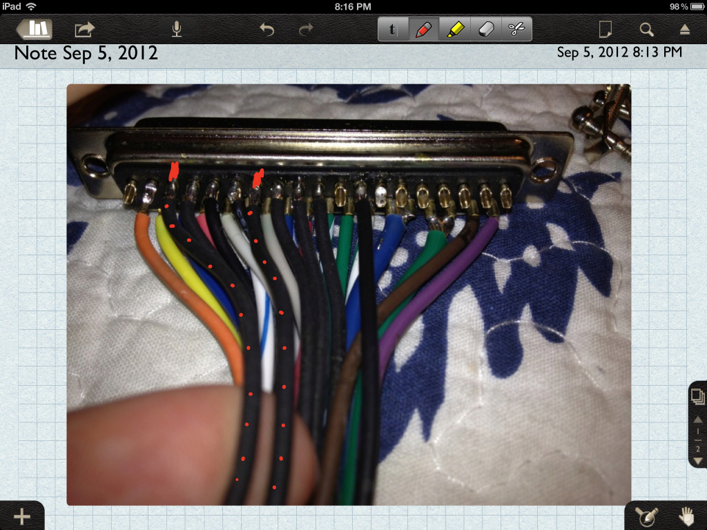
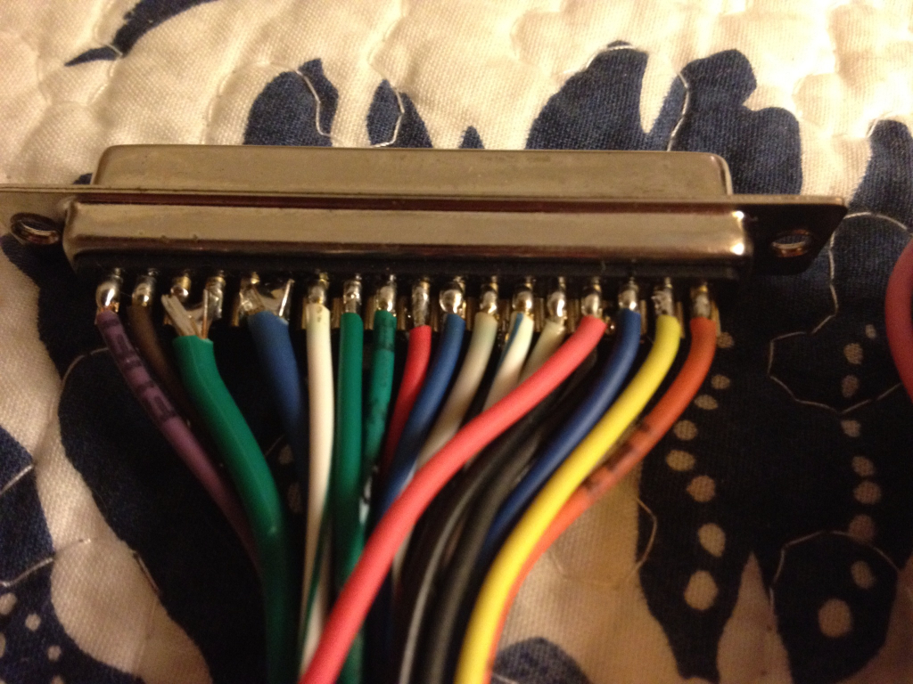
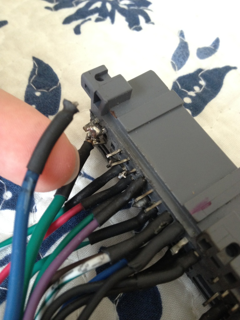
Can you tell me, that thick blue wire on the end of the harness, does it connect to the two outer pins like hte thick green one above it?
Can you tell me, that thick blue wire on the end of the harness, does it connect to the two outer pins like hte thick green one above it?
Reply
0
0
Thread Starter
Senior Member
iTrader: (14)
Joined: Oct 2006
Posts: 677
Total Cats: 6
From: South East Florida
Planning to do the PT7, did not forget.
Added PW1-4 to the third graph. 3&4 are blank. This tell you anything?
Uhhhh, so ummm yeah, I think you might have guessed the problem
Putting this here just in case.
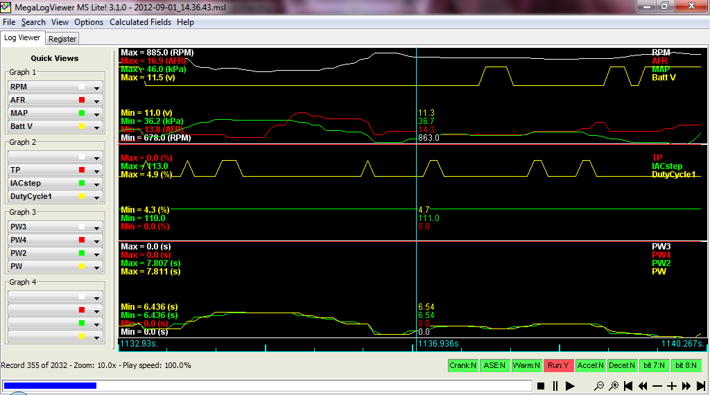
Added PW1-4 to the third graph. 3&4 are blank. This tell you anything?
Uhhhh, so ummm yeah, I think you might have guessed the problem
Putting this here just in case.
Reply
0
0
That batch of gray connectors (probably 2-3 years ago) absolutely STUNK at soldering wires to.
I took his old harness from that of a 91 and converted it to a 99-00 harness. Apparently that wire didnt take. :(
This is why I like the DIYBOB...But I hate the price tag.
I took his old harness from that of a 91 and converted it to a 99-00 harness. Apparently that wire didnt take. :(
This is why I like the DIYBOB...But I hate the price tag.
Reply
0
0
Thread Starter
Senior Member
iTrader: (14)
Joined: Oct 2006
Posts: 677
Total Cats: 6
From: South East Florida
I've given up on soldering. I made contact with MD323, who is local, and he is graciously going to lend a hand. Should be running soon depending on our schedules.
So what does that fat blue wire control? Can you also post the pinout picture for me? I tried finding it in our emails with no luck.
So what does that fat blue wire control? Can you also post the pinout picture for me? I tried finding it in our emails with no luck.
Reply
0
0
it controls two injectors. it should solder to those two pins with the solder blob on them in that picture, directly behind the wire, directly below the green wire with teh same two pins.
Reply
0
0


