
Soldering a PNP harness


Thread Starter
Senior Member
iTrader: (9)
Joined: Sep 2009
Posts: 691
Total Cats: 26
From: Yamato Japan
Ok, so you ordered the tyco plug. You got an MS pigtail. Now you're putting the bitch together to put it in the car...
Any tips on connecting the wires to the pins? It seems like you're supposed to tin the pin, tin the wire, and just kinda... stick them together. It just makes me uneasy with no mechanical anchoring. I feel like I should be twisting the wires to the pins before soldering.
Appreciate suggestions.
Any tips on connecting the wires to the pins? It seems like you're supposed to tin the pin, tin the wire, and just kinda... stick them together. It just makes me uneasy with no mechanical anchoring. I feel like I should be twisting the wires to the pins before soldering.
Appreciate suggestions.
Reply
 0
0

0


Didn't like it either. Especially since each one tugs on it slightly differently, and when you go to mount it, you'll most likely have to twist it. Which is why mine was sent to braineack to be finished for a reasonable price. Or you can solder directly to the harness.
Reply
0
0
Thread Starter
Senior Member
iTrader: (9)
Joined: Sep 2009
Posts: 691
Total Cats: 26
From: Yamato Japan
I'm trying to avoid irreparable wiring changes. I like the whole PNP plug idea.
It's funny, I found making the ms3 itself to be very relaxing/cathartic, the harness/solder cups.... (*^#@!!!!!!!!
It's funny, I found making the ms3 itself to be very relaxing/cathartic, the harness/solder cups.... (*^#@!!!!!!!!
Reply
0
0

Any tips on connecting the wires to the pins? It seems like you're supposed to tin the pin, tin the wire, and just kinda... stick them together. It just makes me uneasy with no mechanical anchoring. I feel like I should be twisting the wires to the pins before soldering.
Reply
0
0

Run to radioshack and pick up some small alligator clips. Straighten all the pins on the connector and cut them to a reasonable length. Now, strip all of the wire ends and twist them tight, then tin them. Tin the connector as well.
Put the connector in a vice or some sort of secure holder. Slide shrink tube over every wire. Pick one end of the connector and clip the associated wire to the correct pin. Solder like a boss. Then slip over the shrink and heat it up.
Blammo.
Edit: You may also want to look into uninsulated crip connectors that are just slightly larger than the pins and wire (enough that you can slide them on, but sort of a tight fit). You can use them to 'bridge the gap' so to speak between the two since both will fit inside. Simply solder them onto the wires, then slip them over the pins and solder there while holding the wire so it doesn't pop out. Then slide up the shrink tube.
Reply
0
0
Thread Starter
Senior Member
iTrader: (9)
Joined: Sep 2009
Posts: 691
Total Cats: 26
From: Yamato Japan
So you are using un insulated crimps, but not crimping? Just filling them with solder? I have a stock pile of those, may try it.
And I wouldn't think of doing this without shrinking every wire, that's just ASKING for it. I also use adhesive lined wrap and pack every joint with dielectric grease. never had an issue with anything I've soldered.
And I wouldn't think of doing this without shrinking every wire, that's just ASKING for it. I also use adhesive lined wrap and pack every joint with dielectric grease. never had an issue with anything I've soldered.
Reply
0
0
 .
.FWIW you could crimp them on the wire, then slide over the pins and solder. Then solder on the wire end and shrink.
Reply
0
0

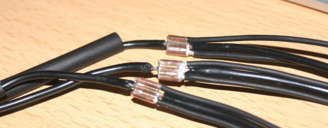
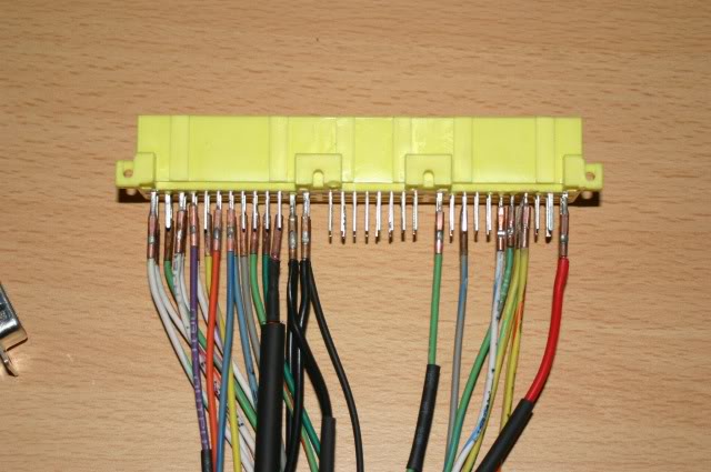
I cut all the pins on the 64 connector to be short little nubs. I tin all the ones I know I'm going to attach to. I tin all the wires I'm attaching. I put heat shrink on each wire and then start left to right attaching them one at a time.
should look nice and clean like this:

not like this:

also dont step on them:

should look nice and clean like this:
not like this:
also dont step on them:
Reply
0
0
Thread Starter
Senior Member
iTrader: (9)
Joined: Sep 2009
Posts: 691
Total Cats: 26
From: Yamato Japan
how do you hold them together? I've found it's very tedious to get them to actually line up. And you just put them side by side and let the hot solder hold them together?
Why is it that every photo of the right way already has shrink over it so we can't observe the solder technique?
Why is it that every photo of the right way already has shrink over it so we can't observe the solder technique?
Reply
0
0


Junior Member
Joined: Mar 2011
Posts: 163
Total Cats: 0
From: Guildford, UK
Here's how I've done my MS3+3X
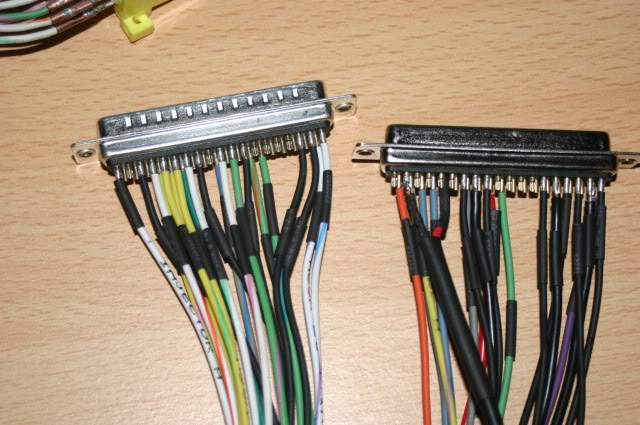
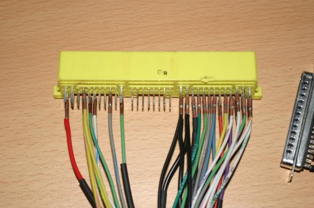
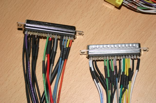
I used 2mm copper tube, will make it easier to swap things around if I've made a mistake.
I would be grateful if someone could check the pin-outs I've chosen, before I heat shrink it all.
Car is a 1995 Eunos, 1.8l
I used 2mm copper tube, will make it easier to swap things around if I've made a mistake.
I would be grateful if someone could check the pin-outs I've chosen, before I heat shrink it all.
Car is a 1995 Eunos, 1.8l
Reply
0
0

Junior Member
Joined: Mar 2011
Posts: 163
Total Cats: 0
From: Guildford, UK
The grounds and ignition are all silver soldered lengths to double up the wires.
Nice idea Ludwig, did get a couple of pins a little warm and the moved a tad. I'll make sure they line up first and than my pinouts are correct before I think about epoxy.
Reply
0
0


Joined: Jun 2005
Posts: 19,338
Total Cats: 574
From: Fake Virginia
the pins on the 2001 connector pull out *from the connection side* which is great because when you inevitably over-flex one of the installed ones and break it, you can just pull another one out and pop it in its place.
i use "helping hands" to hold ****:


and I hot glued the **** after it was done.
i use "helping hands" to hold ****:
and I hot glued the **** after it was done.
Reply
0
0

Thread
Thread Starter
Forum
Replies
Last Post
Zaphod
MEGAsquirt
47
Oct 26, 2018 11:00 PM


