
Started my MS3X build this week, questions to follow


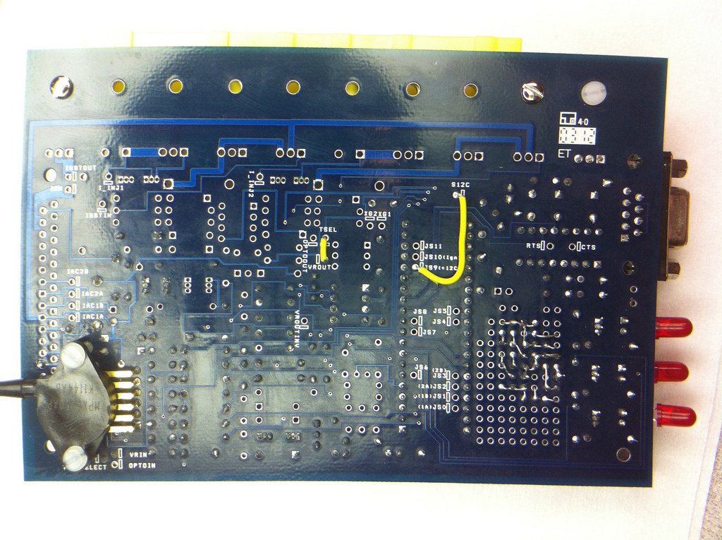
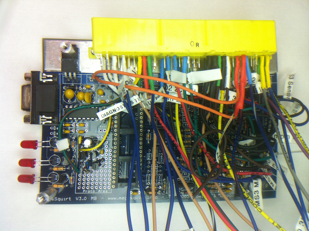
gray lines are traces between pins.
thick gray are jumper wires.
orange are tails.
and then the orange line in question is just another jumper with a piece of wire.
thick gray are jumper wires.
orange are tails.
and then the orange line in question is just another jumper with a piece of wire.
Reply
 0
0

0

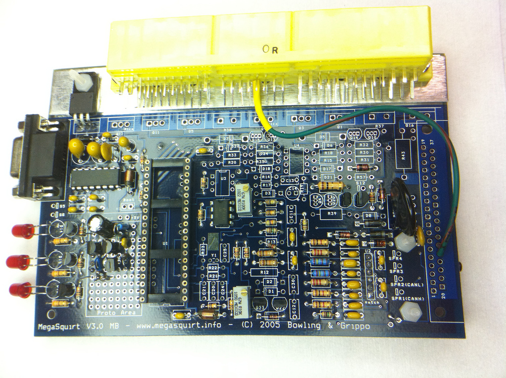
I managed to get the circuit soldered up, but didn't get a chance to run the wires to finish it. I will have to wait until tomorrow.
The circuit was easier to solder up on the proto area than to layout on the Breadboard. I really figured out the circuit through working on it, though.
Another question, 1N4001 needs to terminate in Pin 9 on the MS3X, with the other end to a 12v source. What 12V source? So it goes 12V source (on MS3X?) to pin 9 and then pin 9 to the Tyco connector?
Also, Frank is pretty adamant about grounding wires, do most people run their grounding wires outside of the harness to the engine or just use the harness? I know his application is not a Miata, so he may be doing it a bit differently.
I am not looking forward to soldering the wires to the TYCO connector next. It is a pain to hold the wire/solder/iron in just the right place.
Pictures:
Reply
0
0

Senior Member
Joined: Nov 2007
Posts: 999
Total Cats: 73
From: Belgium
Yeah, once you figure it out, it's really not that hard. Any 12V source will do actually, but as it's a flyback diode (high currents possible) I felt it safer to solder it on the Tyco connector, not on the board itself. I soldered the diode directly between Tyco pin 1B and Tyco pin 30 (see the 'Frank' diagram). I used the stock harness. The seperate sensor ground is already there on a miata and there are multiple seperate ground wires to the engine, so a stock miata harness is good enough as is.
Reply
0
0
Thanks for the answer. I kind of researched it further and got my answer, but you made it totally clear. The DB37 on my MS3x card was a pain to get out. I think some of the solder had the flux baked out of it and would not reflow. I had to add solder back on and try to suck it out, which took forever.
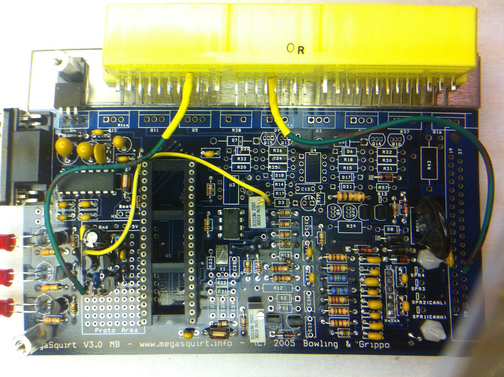
I made some progress, here are some photos. I keep posting photos to hopefully help others have fewer questions when they decide to build a(n) MS3.
I made some progress, here are some photos. I keep posting photos to hopefully help others have fewer questions when they decide to build a(n) MS3.
Reply
0
0
Senior Member
Joined: Nov 2007
Posts: 999
Total Cats: 73
From: Belgium
looking good so far.
A tip, when you start soldering wires to the tyco connector, start with the bottom row, not the top row (bottom row will be blocked off). And another tip. Don't bother building the low batt warning light. Use a spare output to activate the low batt light, like when Vbatt is lower then 12V or higher than 15.5V or so.
A tip, when you start soldering wires to the tyco connector, start with the bottom row, not the top row (bottom row will be blocked off). And another tip. Don't bother building the low batt warning light. Use a spare output to activate the low batt light, like when Vbatt is lower then 12V or higher than 15.5V or so.
Reply
0
0
tin the connector pin then tin the wire. hold the iron on the pin, get the solder wet, then touch the wire onto it and have it all melt together....release iron, hold wire in place.
that will make sure you get the best bond, those pins dont like to be soldered poorly.
that will make sure you get the best bond, those pins dont like to be soldered poorly.
Reply
1
1
Good point. I will go left to right (right handed) on the bottom row and then same for the top.
Thanks for letting me know about using a spare output for Vbatt (is pin 20 okay, or are there problems with using injector pins?). I also need to setup another input/output for my A/C. Do you know what most people use? I was thinking Nitrous? Pins 25 (output) and 29 (input).
Just have to make sure the amperage is adequate and change the software to have that pin affect the MS? This is a basic question that isn't exactly answered in one place- All of the inputs are either switched 12V or a setup to monitor a sensor (ADC?)?
Reply
0
0

Newb
Joined: Feb 2012
Posts: 4
Total Cats: 0
From: Phoenix, AZ
Good point. I will go left to right (right handed) on the bottom row and then same for the top.
Thanks for letting me know about using a spare output for Vbatt (is pin 20 okay, or are there problems with using injector pins?). I also need to setup another input/output for my A/C. Do you know what most people use? I was thinking Nitrous? Pins 25 (output) and 29 (input).
Just have to make sure the amperage is adequate and change the software to have that pin affect the MS? This is a basic question that isn't exactly answered in one place- All of the inputs are either switched 12V or a setup to monitor a sensor (ADC?)?
Thanks for letting me know about using a spare output for Vbatt (is pin 20 okay, or are there problems with using injector pins?). I also need to setup another input/output for my A/C. Do you know what most people use? I was thinking Nitrous? Pins 25 (output) and 29 (input).
Just have to make sure the amperage is adequate and change the software to have that pin affect the MS? This is a basic question that isn't exactly answered in one place- All of the inputs are either switched 12V or a setup to monitor a sensor (ADC?)?
I am am at the same spot as you in trying to figure out the a/c inputs and outputs. I understand which pins on the ms3/x i need to be using I just do not know which pins on the tyco ecu connector I am supposed to be connecting those to. Braineack said that the a/c switch switched to ground when turned on, so would it be wrong to assume that I can just heck continuity of all the tyco pins with ground and find the one that matches when the a/c switch is pressed?
Other than that my car is currently running with Frank's build and with the alternator circuit, I just need a/c because it is getting hot QUICK here in AZ!
Reply
0
0
1P is your a/c switch into, that you'll bring into the ms3x.
then youll connect 1S, 1I to a spare INJ output on the ms3x to trigger the a/c compressor and a/c fan relays.
then youll connect 1S, 1I to a spare INJ output on the ms3x to trigger the a/c compressor and a/c fan relays.
Reply
0
0
Newb
Joined: Feb 2012
Posts: 4
Total Cats: 0
From: Phoenix, AZ
okay so i am really confused now. going off of what you said and what other people have said in this thread this is what i did. I jumpered the a/c fan 1I with the normal fan and then i connected the nitrous in to 1p and my nitrous 2 output into 1s. With this configuration the ac turns on at idle only when the a/c switch is off or when the fans are set to 0. When driving however the a/c stay permanently on. I am not sure where I went wrong here
Reply
0
0
Newb
Joined: Feb 2012
Posts: 4
Total Cats: 0
From: Phoenix, AZ
Hmm well i guess I will unjumper that then. What settings would you use assuming that I used the pins you specified? Sorry if this is a stupid problem, this has really been the only part of the build that has gotten me stumped though.
Reply
0
0
I had to take a break while on a trip in the UK. I tried to finish before I went, but had to stop with 10 wires on the harness left to go (at least they are the easy ones). I will post an update later.
Any updates on the above question about A/C? A tiny bit of spoon feeding may help having to take the megasquirt back out one more time when I am getting it fitted. I understand it all in theory, but reality seems much simpler.
Any updates on the above question about A/C? A tiny bit of spoon feeding may help having to take the megasquirt back out one more time when I am getting it fitted. I understand it all in theory, but reality seems much simpler.
Reply
0
0
I have finished the harness, the picture below is before soldering the MS3x. No real roadblocks, just a couple long nights with the car's wiring diagram. I know I can just follow the guide step by step, yes- it is that good for getting a car running, but I wanted to know what I was actually doing. The case will be a tight fit with the amount of wire I used.
I wired the flyback diode (3O) and IAC (3M) to pin 2 on Q12, that should not be a problem, or am I missing something?
I labeled everything. I would recommend it to anyone, it is a pain and it makes everything take longer, but the result is a harness that is easily modified and double checked.
A/C setup: 1S to MS3x pin 4 (INJ F), 1I to MS3x pin 7 (INJ E), and 1P to MS3x pin 11 (Launch-in). It seems that there are very few Switched Ground inputs, so I will go without launch control.
Now, I try to get the case modified and plugged into the car as soon as possible.
Reply
0
0
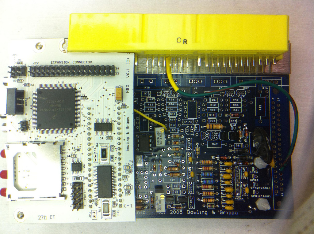
I was reading in another thread about the flyback diode.
Is my placement okay, in experience? In theory it should be fine. The diode is in the thicker portion of heatshrink wrap on the TYCO connector.
I have been too busy to get this thing in the car. Hopefully I get some free time this weekend. I tried to update it with a bench power supply but gave up. I will do it in the car. Still need to unplug the coils, right?
5/32" vacuum hose for the MAP sensor? Is silicon hose worth it for <16PSI max boost? About 10' (3m) enough for a '99? Anyone recommend a vacuum tee for coming off the back/top of the intake manifold (or at least the size hose coming off the manifold)?
Reply
0
0

Great write-up so far!
Since it looks like I will be going that exact same route in a few weeks, I really appreciate not having to make ALL the mistakes myself, but having somebody make some of them for me first.
Which wiring diagram did you end up using, or did you make one of your own?
Since it looks like I will be going that exact same route in a few weeks, I really appreciate not having to make ALL the mistakes myself, but having somebody make some of them for me first.
Which wiring diagram did you end up using, or did you make one of your own?
Reply
0
0

Alright, I finally got some time to get this thing in order. I had a little home improvement project get in the way.
I had to install an LC-1, new header, and midpipe. I also extended my narrowband rear wiring. I have to leave the car able to run on its own ECU for CA smog.
Tips on grounding the LC-1:
When you pull your vacuum line through the firewall, tape 6 wires to it. Leave 3 long enough to bolt to the intake manifold for wideband grounding, and the other 3 so you don't have to do it again when you do sequential spark.
Buy good electrical tape and the plastic wire shielding to make your own protective loom. Take the time to solder and shrink wrap. Do a good enough job so that it looks better than factory.
After all of this, I finally was ready to install the MS3. First I had to find how to unplug the coils. I searched using every combination of words I could think of and came up with nothing. I knew about the plugs on the coil, but there had to be another plug to the harness. I looked, followed, and checked the wiring diagram. I needed the brn/yellow,yellow,black/white,black wired connector is what I discovered and followed it to in front of the throttle body next to the valve cover. Right of the injector plug. Hopefully, someone with an NB will be able to use this info and save themselves 30 minutes to an hour.
I also discovered that my plug wires had corroded to the coil plug (any solution to this?) Time for new wires.
I finally plugged in the MS3x opened tuner studio and it found it! I loaded the Beta 24 firmware. Changed some conflicts and everything was reading as it should with the car off. TPS/CLT/IAT/MAP all reading what they should. I loaded Franks base map, too.
Tonight I hope to go through the settings and check everything, with the goal to start it tonight.
Are there any changes to the settings between MS2 and MS3 as far as setup on an NB?
Anyone have a base tune that is better than Frank's?
Do I need to verify base timing still, even using the stock cam sensor???
Reply
0
0


