
Tach doesn't work w/MS & Cops, did 1k resistor trick already


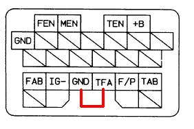
I've soldered in the 1k resistor between +B and IG where their wires come off the diag box, didn't help. Confirmed 12v between IG and ground pins in the black connector that goes into the gauge cluster. Have continuity in that wire all the way from that connector to the yellow/green pin of the ignitor clip.
since I've got another NA, swapped in the gauge cluster from the other car, but no change. Also tried disconnecting the gutted ignitor of the COPs and snapping on a stock ignitor, which in theory would have showed 200 revs or so as the car tried to crank.
I do have illumination on the cluster (though only when headlights come on, not when parking lights come on?) Also odd is that the blue high beam light is on no matter if the high beams are actually on or not. During this build, a few months ago I was installing new headlights, and found that they were very dim in low beam, and didn't work in high beam, and ultimately I found that my combination switch required cleaning, which I did, adding dielectric grease to prevent it needing done again in the future. That fixed the lights, but I don't know if it's related to this. The turn signals do work.
the oil pressure gauge works, and the various information lights. Fuel seems to, and I don't have the stock water temp gauge installed. The HVAC fan works, which rules out a common screw up others have done, mixing up dash connectors on the right side of the dash under the fan. No burnt traces on cluster.
Checked all ground points under dash and in bay, checked all fuses for continuity. Also used multimeter to make sure I'd joined the yellow/green and black/white wires inside the gutted ignitor, as shown in cops diagram, and I had.
Last resort would be to run a wire from the MS's tach input (ms reads tach fine) straight to the tach. But would rather not.
Anyone have any other ideas?
Reply
 0
0

0


I had issues with my tach not working. I was frustrating. I decided it was simpler to go to Radioshack, buy a 2N2222A transistor and build a tach output circuit on my megasquirt.
Reply
0
0
Interesting, soviet. Did you follow a guide from somewhere, or are you just that good with electronics?
If you had to build a circuit, I'm guessing that my idea of tapping into the ecu's tach signal pin and just sending it straight to the gauge cluster won't work.
If you had to build a circuit, I'm guessing that my idea of tapping into the ecu's tach signal pin and just sending it straight to the gauge cluster won't work.
Reply
0
0
at the diag box, IG- to any ground point has 001 continuity, however at the the gauge cluster connector, I get 027 between IG and any ground. Also measured continuity between the IG wire at the diag port and the IG wire at the gauge connector, and that was 027 as well. Maybe the wire degraded somewhere between the diag connector and the cluster?
Also, I'm pretty sure, based on similar threads, that "tachometer output" should be "off" for my 1.6l, as was its default. Just confirming..
Also, I'm pretty sure, based on similar threads, that "tachometer output" should be "off" for my 1.6l, as was its default. Just confirming..
Reply
0
0
I dunno about what your megasquirt has but....
The tacho circuit is 2 resistors an a transistor. I took 12V from S12C on the board and used J5 as Megasquirt output pin. Then built the circuit in the proto area and wired tach output to pin 2X on the harness, normally used for "Purge Solenoid". Under the hood I soldered the purge solenoid wire to the tach output wire that normally comes from the ignitor. They are conveniently located next to each other.
Then enable Tacho Output in Tunerstudio and choose JS5 pin. DONE!
tach output circuit: https://www.miataturbo.net/showpost....16&postcount=4
Reply
0
0
Something has to be wrong with my wiring, with the high beam indicator bulb staying lit no matter if the high beams are on or not, and the gauge cluster illumination only being on when the headlights are fully on, but not the parking lights. The light on the dimmer goes on when in the parking light position. I'm going to check my combo switch.
Reply
0
0
*** edit, **** I'm dumb. thought I'd found a cop that was different than the other three, but for some reason the polarity of my continuity check mattered.
Last edited by tronik; Sep 29, 2011 at 11:48 PM.
Reply
0
0
So my tach problem isn't the combo switch, or anything else electrical. The strange cluster behavior with the high beam indicator bulb was a bad flasher, which I fixed with cleaning and reflow of the solder.
So I'm going to go with the tach circuit built onto the megasquirt pcb. I've got the 2N2222A transistor, and brainy's circuit diagram, but am unclear on a few things - First is which legs of the transistor go to the 12v and which gets the tach input. Below is what it looks like to me

question marks on tach source and 12v, because I cannot find S12C anywhere on the board, either side. Can it be any labeled 12v source? Neither can I find J5/JS5 (I'm assuming they are the same point) that will be the MS's tach input to the transistor. I may have a different revision board than you, soviet. Here are a bunch of high res pics of my board - no one pic is all inclusive I'm afraid
So I'm going to go with the tach circuit built onto the megasquirt pcb. I've got the 2N2222A transistor, and brainy's circuit diagram, but am unclear on a few things - First is which legs of the transistor go to the 12v and which gets the tach input. Below is what it looks like to me
question marks on tach source and 12v, because I cannot find S12C anywhere on the board, either side. Can it be any labeled 12v source? Neither can I find J5/JS5 (I'm assuming they are the same point) that will be the MS's tach input to the transistor. I may have a different revision board than you, soviet. Here are a bunch of high res pics of my board - no one pic is all inclusive I'm afraid
Reply
0
0
you labeled it wrong. even if you do find s12c, it won't work 
(I'll give you a hint, swap C and E)
Also, I don't know how to break this to you, but because you have yourself a Brain built diypnp, the tachout circuit is already built in within the uS module...
This means you just need to jump TACH to an open spot on the DB15 and run the wire out from it to the dash wire. In the software, all you need to do is turn it on and set the output to TACHOUT.
also are you absoultely certain you put the resistor in the right spot? And why did you solder? ...You just needed to jump across the two pin, so all you need ot do is bend the resistor into a U shape and make sure they fit into the contacts.
But if you did, it's possible your ignitor is going south.
Last edited by Braineack; Oct 6, 2011 at 09:13 AM.
Reply
0
0

Thread
Thread Starter
Forum
Replies
Last Post
JacksonRacingEngines
Engine Performance
10
Sep 10, 2015 09:52 AM
db84drteg
MEGAsquirt
10
Sep 24, 2007 09:31 AM


