
Wee wiring problem on my Ute build


Thread Starter
Junior Member
iTrader: (1)
Joined: Dec 2008
Posts: 72
Total Cats: 0
From: Land down Under
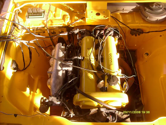
Well after a few major set backs like a busted knee and the passing of my daughter this year , i finaly had time to shoe horn the 1.6 miata motor into my little ute
(photo attach) which was a big friggen head ach lol but not as much as i am having working out the wiring for this project. Now i am using a megaquirt 2.2 and because
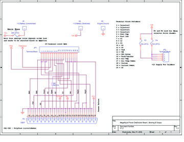
this ute is new to fuel injected engines i thought i would go with a Megasquirt Power distribution Board and harness from DIYAutoTune but i having problems getting my head around it in setting it up, and i would like to ask you guys for your imput. First off i am using part of the orginal loom from a mx5 engin bay ie: the injectors, coils, igniter,and sensors.
Ok the coils there is a large Blue wire coming of the harness now i know this is power can i connect this to the ignition ?? without a fuse or should i add one ??
Next is the igniter also a large blue wire which i assume would go to the same place as the Coils one would go, there is 3 other wires i have concerns about, a b/w,a br/y, a br, now i know these 3 wires go to the factory ECU but how do i work out where they go on the Megasquirt Power distribution Board. And there is a Tach wire as well coming out of the igniter, but there is a tach output on the distribution Board.
Now for the injectors, the distribution Board has 4 signal connectors and 4 power connectors for the injectors, as you guys would know there is only 3 wires 1 power and 2 signal wires, so what would you reconmend in wiring this up ??
As for the CAS that has me totaly baffled, there a 4 wires coming out of it as the schematic show 3 of them go to the factory ECU but bugger if i know how i am suppose to wire it in to this distribution Board ?
As i am using the distribution board (relay board) it has its own Relay Cable which connect between the megasquirt and the distribution board and there does not seem any other way to connect more bits to the megasquirt other then though the relay board ??.
Now just one more i have been reading post on the forum but alot are not to clear, if i want to remove the factory AFM can i just replace it with the IAT sensor kit from DIYAutoTune.
Any help or directions would be very appreciated
Cheers
Dr.

(photo attach) which was a big friggen head ach lol but not as much as i am having working out the wiring for this project. Now i am using a megaquirt 2.2 and because
this ute is new to fuel injected engines i thought i would go with a Megasquirt Power distribution Board and harness from DIYAutoTune but i having problems getting my head around it in setting it up, and i would like to ask you guys for your imput. First off i am using part of the orginal loom from a mx5 engin bay ie: the injectors, coils, igniter,and sensors.
Ok the coils there is a large Blue wire coming of the harness now i know this is power can i connect this to the ignition ?? without a fuse or should i add one ??
Next is the igniter also a large blue wire which i assume would go to the same place as the Coils one would go, there is 3 other wires i have concerns about, a b/w,a br/y, a br, now i know these 3 wires go to the factory ECU but how do i work out where they go on the Megasquirt Power distribution Board. And there is a Tach wire as well coming out of the igniter, but there is a tach output on the distribution Board.
Now for the injectors, the distribution Board has 4 signal connectors and 4 power connectors for the injectors, as you guys would know there is only 3 wires 1 power and 2 signal wires, so what would you reconmend in wiring this up ??
As for the CAS that has me totaly baffled, there a 4 wires coming out of it as the schematic show 3 of them go to the factory ECU but bugger if i know how i am suppose to wire it in to this distribution Board ?
As i am using the distribution board (relay board) it has its own Relay Cable which connect between the megasquirt and the distribution board and there does not seem any other way to connect more bits to the megasquirt other then though the relay board ??.
Now just one more i have been reading post on the forum but alot are not to clear, if i want to remove the factory AFM can i just replace it with the IAT sensor kit from DIYAutoTune.
Any help or directions would be very appreciated
Cheers
Dr.

Last edited by drbogg; Nov 25, 2009 at 01:12 AM. Reason: added pic
Reply
 0
0

0
Thread Starter
Junior Member
iTrader: (1)
Joined: Dec 2008
Posts: 72
Total Cats: 0
From: Land down Under
well thanks for the input on some of my problems, it seems i have been able to sort some of the wiring out, but still have a problem with a wire or two manly the White/red wire which is 28 on the DB37 connector which is marked 12 RAW ok i worked out to be 12 volt power which is need ed for the igniter and the CAS (white/Red wire) but where to get this from the relayboard
I suppose i will work it out in the long run, the worst thing that could go wrong is i set the car on fire lol.
Cheers
Dr.Bogg
I suppose i will work it out in the long run, the worst thing that could go wrong is i set the car on fire lol.
Cheers
Dr.Bogg
Last edited by drbogg; Nov 26, 2009 at 06:21 AM.
Reply
0
0

You might talk to.. fred - rb26dett - he's a kiwi who put an FE3 into a ute with a megasquirt, and did an amazing job. Look up his posts and check out the build pics in his signature.
Reply
0
0
Thread Starter
Junior Member
iTrader: (1)
Joined: Dec 2008
Posts: 72
Total Cats: 0
From: Land down Under
Cheers
Dr.
Reply
0
0
Thread Starter
Junior Member
iTrader: (1)
Joined: Dec 2008
Posts: 72
Total Cats: 0
From: Land down Under
well i got all my wiring sorted and added a LC 1 wideband to the setup as well. now i have tried to read up and search around the place to get more info on my next problem that has pop up, and i did not want to bother you guys about as this is not really a miata, but i have not been able to sort it out so i am taking a deep breath and asking for help, When i crank this engine over i am not getting any spark at the plugs, i have power at the coils and ignitor and thats it also showing in megatune a very high MAP ?.
i have used the MSPNP_MM9093 no AFM base map and configered it for my engine.
i have attached my datalog and msq if you would like to have a look.
Cheers
Dr.
i have used the MSPNP_MM9093 no AFM base map and configered it for my engine.
i have attached my datalog and msq if you would like to have a look.
Cheers
Dr.
Reply
0
0
Thread Starter
Junior Member
iTrader: (1)
Joined: Dec 2008
Posts: 72
Total Cats: 0
From: Land down Under
anyone ?? come on guys throw a Desperate man a bone here, my squirt works ok and shows spark when using a stim, but no spark when wired up to the ignitor and coil pack though the relayboard, i have followed the wiring diagram outlined in '90-'93 MS1 Standalone wiring diagram that Joe Perez posted up, i must be doing something wrong, or as i said before maybe the ignitor is dead, if it was it would not give me a tach signal in mgatune when cranking ???.
Cheers
Dr.
Cheers
Dr.
Reply
0
0

Thread Starter
Junior Member
iTrader: (1)
Joined: Dec 2008
Posts: 72
Total Cats: 0
From: Land down Under
Thanks Braineack, I have already unpluged the TPS and i will change the middle LED circuit to fan control when i get home tonite.
Thanks heaps for your imput on this problem i am trying my best to do this stuff myself as i know you guys don't like dumb newbies like myself, but where i am located no one knows this stuff and when i do ask them they give me a dumb look and say mega what ??.
Cheers and merry xmas
Dr.
Thanks heaps for your imput on this problem i am trying my best to do this stuff myself as i know you guys don't like dumb newbies like myself, but where i am located no one knows this stuff and when i do ask them they give me a dumb look and say mega what ??.
Cheers and merry xmas
Dr.
Reply
0
0

Thread Starter
Junior Member
iTrader: (1)
Joined: Dec 2008
Posts: 72
Total Cats: 0
From: Land down Under
ok thanks guys for the help, First i am using a MegaSquirt-I PCB2.2 board with the mods outlined below,
""CMP Signal" -- Lay a 1k 1/4watt resistor across the bottom of the PCB with one end at pin 11 of the processor (U1) and the other end at the X11 hole. Bend the resistor leads to raise the resistor just a bit off of the PCB and allow a lead on one end to drop through X11 and solder that end in place (while making sure the other end is in place near pin 11 still, and with the resistor still raised a bit off the board so the leads don't short against anything). Then use needle-nose to hold the resistor lead to pin 11 and solder it to the pin. Now to get the 5v pullup use a 470 ohm 1/4w resistor and solder one end of it to the first resistor at X11 (just tie them together) and the other leg of it to the small unlabeled hole just above and to the right of D9 (when looking at the PCB from the top that is). Do not connect to the leg of D9 itself - you will be using a small hole in between D9 and R13. Once again raise this just enough off of the PCB to prevent it from shorting with any of the leads sticking out on the board. (Heatshrink tubing over the whole wire/resistor assembly works nicely)
The new "cap mod" turns this into a low pass filter that helps avoid misfires caused by a noisy CMP signal. Solder a length of wire to a 0.1 uF capacitor, and connect this capacitor-on-a-wire between pin 11 on the processor and a ground point. The second hole from the bottom on the JP1 header is a good ground point.
"CKP Signal" -- We just need a 12v pullup. Install a 470ohm 1/4w resistor between the right side (non-band) end of D5 and the right hole (banded) end of D9."
i am thinking i may be better off upgrading to a new version ?
Ampz thanks for the offer i am in Adelaide a wee bit far to drop by lol
Cheers
Dr.
Last edited by drbogg; Dec 15, 2009 at 01:43 AM.
Reply
0
0
Thread Starter
Junior Member
iTrader: (1)
Joined: Dec 2008
Posts: 72
Total Cats: 0
From: Land down Under
Well gave up on the MegaSquirt-I PCB2.2 board got myself a MS1 PCB V3 board followed Braineack instructions and was able to get it running (like a horse with a broken leg) so now i need to do some more reading so i can tune it and get fan mod to work as he Suggested in this thread. Man i was so stoked when it fire up i nearly sh*t myself lol.
Cheers
Dr,
Cheers
Dr,
Reply
0
0

Thread
Thread Starter
Forum
Replies
Last Post
Zaphod
MEGAsquirt
47
Oct 26, 2018 11:00 PM


