
MSPNP not reading AEM failsafe WB

Thread Starter


Joined: Oct 2005
Posts: 15,197
Total Cats: 1,398
From: Oregon City, OR
I installed a 1st gen MSPNP 9093 in a friend's '90 (intercooled greddy with RX-8 425s, if that makes a difference) using an AEM failsafe WB/boost gauge combo, cause he liked the idea of less gauges.
AEM Electronics Wideband Failsafe Gauges 30-4900 - SummitRacing.com
It's reading correctly on the gauge, and it is kinda cool, cause the outer ring can display in LEDs either boost or AFR, and the inner readout can display either boost or AFR. Neat!
However, we CANNOT get the MSPNP to read ANYTHING. Both Tunerstudios and Megatune are configured to be reading a AEM uego, and both are stuck on 9.72 afr (gauge 2 is stuck on 8.84 if that matters). We have tried using both the center connector pin 10 WB input, and using the stock NB for WB input. Either way, the gauge NEVER budges.
Note: the gauge also has a 0-5v MAP output.
I've used my multimeter and confirmed that the white wire delivers a 0-5v signal, so does the yellow MAP output wire. Neither have made the gauges in TS or MT budge.
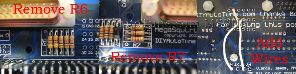
I recently took it apart to replace the transistor that blew when the PO left the ST fuse in. The fuel pump now briefly primes upon powering up as it should. I did notice the ECU was modified to accept a VTPS. These modifications were made:
What am I missing?
AEM Electronics Wideband Failsafe Gauges 30-4900 - SummitRacing.com
It's reading correctly on the gauge, and it is kinda cool, cause the outer ring can display in LEDs either boost or AFR, and the inner readout can display either boost or AFR. Neat!
However, we CANNOT get the MSPNP to read ANYTHING. Both Tunerstudios and Megatune are configured to be reading a AEM uego, and both are stuck on 9.72 afr (gauge 2 is stuck on 8.84 if that matters). We have tried using both the center connector pin 10 WB input, and using the stock NB for WB input. Either way, the gauge NEVER budges.
Note: the gauge also has a 0-5v MAP output.
I've used my multimeter and confirmed that the white wire delivers a 0-5v signal, so does the yellow MAP output wire. Neither have made the gauges in TS or MT budge.
I recently took it apart to replace the transistor that blew when the PO left the ST fuse in. The fuel pump now briefly primes upon powering up as it should. I did notice the ECU was modified to accept a VTPS. These modifications were made:
What am I missing?
Reply
 0
0

0

Thread Starter
Joined: Oct 2005
Posts: 15,197
Total Cats: 1,398
From: Oregon City, OR
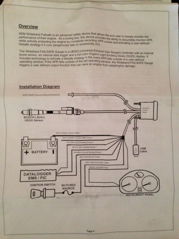
Here are the gauge's wiring instructions. As you can see, the brown wire is setup to output a NEGATIVE 0-5v, and according to the instructions, it appears that an AEM ECU uses both the -5-0v signal (brown) and 0-5v signal (white) in combination to get a clear signal. Perhaps to filter out noise?
According to the instructions, "The brown wire should be connected to an analog ground input for best results. If the [MS] does not have an analog ground input, the brown wire should be connected to a sensor ground. If no sensor ground is available, the brown wire should be connected to a power ground."
So, since the MS doesn't have a analog ground input, I take that as saying the brown wire should be grounded. During our testing the brown wire was at one point hooked into the MS, would this blow anything up?
Our final testing had the brown wire grounded to the chassis, and we were trying everywhere to get the white wire to send a signal to the MS. Wasn't happening.
Reply
0
0
Thread Starter
Joined: Oct 2005
Posts: 15,197
Total Cats: 1,398
From: Oregon City, OR
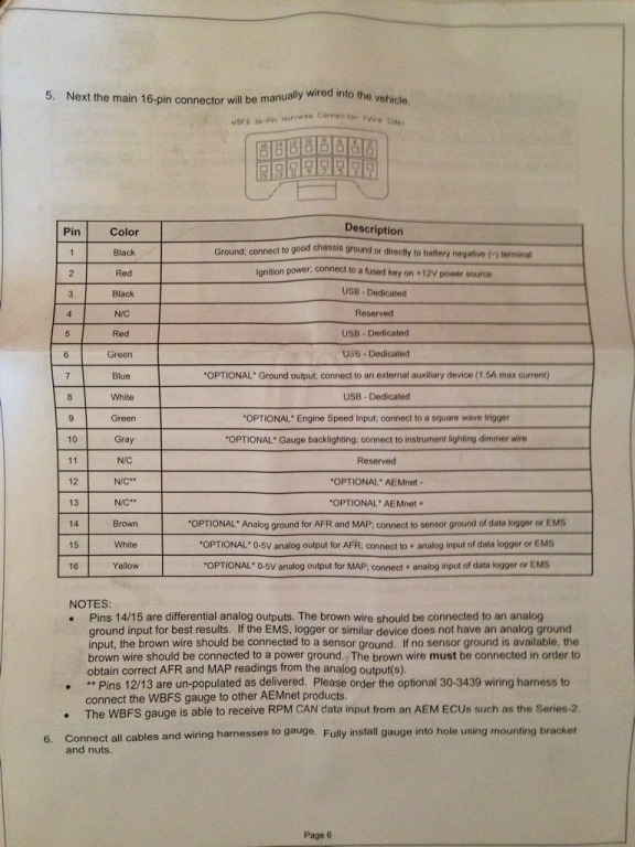
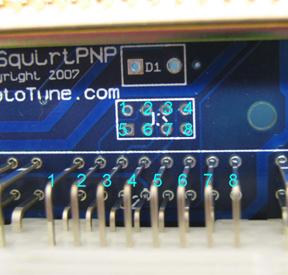
In this photo, it is the bottom row, 2nd one from the left, correctly? Top row is 1-8, bottom row is 9-16?
And, even if I were using the incorrect wire, why would the stock NB wire not work? Is that why there is a AFR and AFR2 gauge? We were looking at both during all the testing.
And, even if I were using the incorrect wire, why would the stock NB wire not work? Is that why there is a AFR and AFR2 gauge? We were looking at both during all the testing.
Reply
0
0
The top pins are numbered 1 through 8, left to right, and the bottom pins are
numbered 9 through 16.
Reply
0
0
Thread Starter
Joined: Oct 2005
Posts: 15,197
Total Cats: 1,398
From: Oregon City, OR
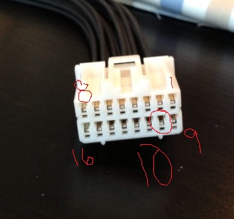
So the negative output signal should go to the black/lt green wire of the MS? Is it easier to just vampire tap into the connector by the MS, or go through the firewall to the NB o2 wire?
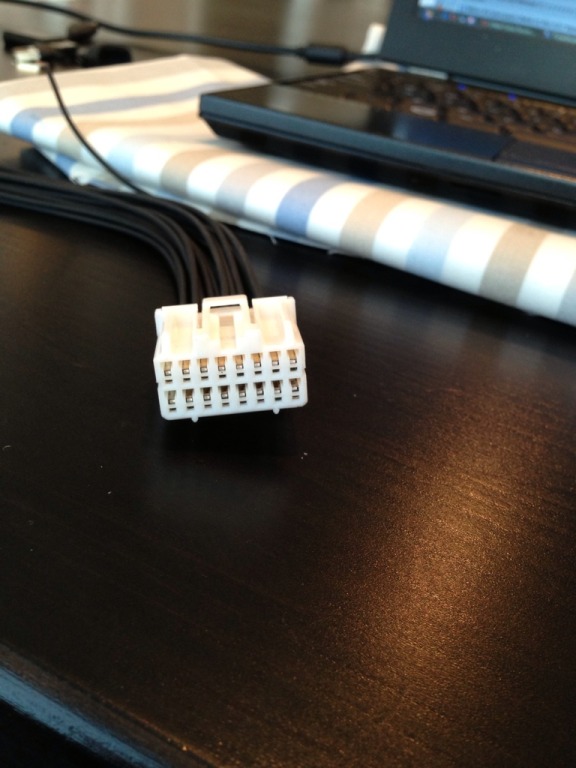
Actually, I looked at the back of the connector, and grabbed the 2nd from the left of the bottom row.
Using the description I typed in post #4, that would be pin 15.
Using the description I typed in post #4, that would be pin 15.
Reply
0
0

So the negative output signal should go to the black/lt green wire of the MS? Is it easier to just vampire tap into the connector by the MS, or go through the firewall to the NB o2 wire?
Reply
0
0
Thread Starter
Joined: Oct 2005
Posts: 15,197
Total Cats: 1,398
From: Oregon City, OR
Ok, so I'll tap the brown into the black/green wires, and according to your expertly drawn wiring diagram above, I was using the correct pin 10. I still feel like the gauge should have budged.
Any other ideas?
Any other ideas?
Reply
0
0
Thread Starter
Joined: Oct 2005
Posts: 15,197
Total Cats: 1,398
From: Oregon City, OR
Yes, controller is reading awesome AFRs for a turbo car, smoothly from mid 15s to mid 11s in boost. Car feels amazing.
MS reads 9.72 and not a .0000000001ths change in all our testing.
MS reads 9.72 and not a .0000000001ths change in all our testing.
Reply
0
0
Thread Starter
Joined: Oct 2005
Posts: 15,197
Total Cats: 1,398
From: Oregon City, OR
Here's the current .msq if that helps.
I've changed the TS project properties to AEM's wideband, and the Exhaust Gas Settings to wideband. In MegaTune I used the configurator to set it to AEM's gauge, and changed the same settings in Exhaust Gas Settings as above. AFAIK, those are the only software related changes required.
I've changed the TS project properties to AEM's wideband, and the Exhaust Gas Settings to wideband. In MegaTune I used the configurator to set it to AEM's gauge, and changed the same settings in Exhaust Gas Settings as above. AFAIK, those are the only software related changes required.
Reply
0
0

Thread
Thread Starter
Forum
Replies
Last Post
StratoBlue1109
Miata parts for sale/trade
21
Sep 30, 2018 01:09 PM
stoves
Suspension, Brakes, Drivetrain
5
Apr 21, 2016 03:00 PM


