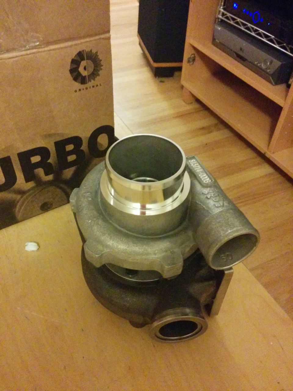
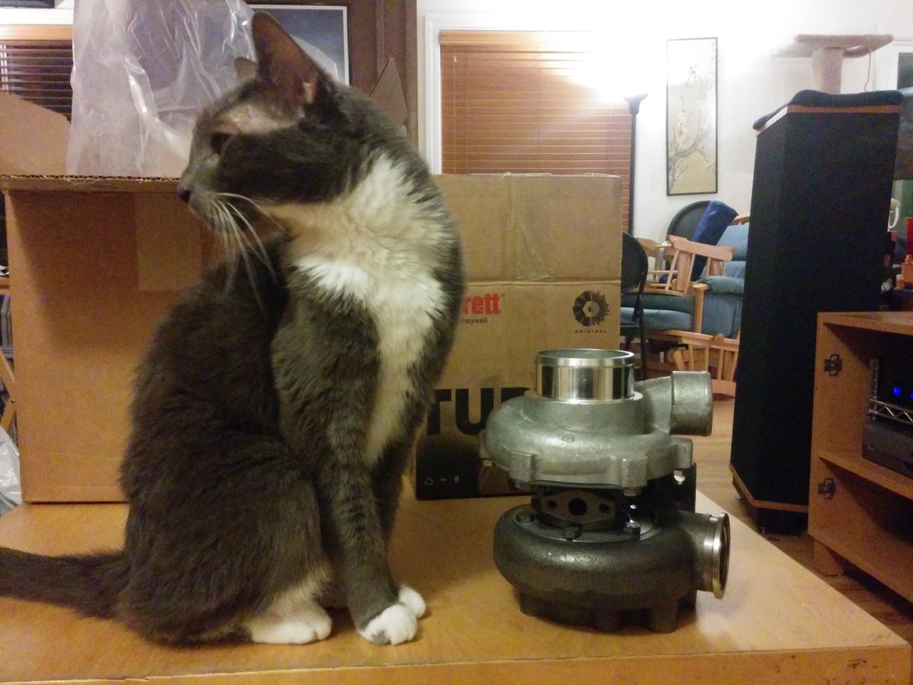
Melted turbine wheel?
#41
Next step up I could find is 100 G's. Too much?
I also like the analog outputs. You could go and capture a data stream, but it'll be around 3 kHz x 3 axes, and then you'd have to process the data, filter it, and extract the amplitudes and frequency (RPM). And log MAP too. With an analog output and a simple AM circuit, you get a simple 0-5V signal you connect to an aux input of an ECU.
I also like the analog outputs. You could go and capture a data stream, but it'll be around 3 kHz x 3 axes, and then you'd have to process the data, filter it, and extract the amplitudes and frequency (RPM). And log MAP too. With an analog output and a simple AM circuit, you get a simple 0-5V signal you connect to an aux input of an ECU.
I would expect the SHAFT access to be bigger, and the body to be smaller, so what might happen is the board for the TB, and the chip for the shaft, and get that chip in a wider range. The thing is, we're not really concerned with if it's 11.6 or 11.9 G's, we're wondering if it's 5, 25 or 50... So low resolution shouldn't be a problem.
There didn't seem to be anything on the actual card, was there? 3 resistors was all I saw, which means it's just a question of Heroic Soldering to get it as a loose sensor.
If we come up with something quick, I'll go ahead and order it. I'm happy to use your circuits for readout (it doesn't seem like anything crazy, but I'll take the work over someone who does it often over someone who has done 4 in his life), probably save me some development time.
I wonder how many free ADC's there are left on the MS - I can read it out with an o-scope or something, but as you said, it'd be nicer to have it tied at least to RPMs... Actually, the MS can't sample that fast, can it? We'd need at least 600 Hz to get 9k rpm at Nyquist.
#42
Oh, duh! I have a board with like 60 channels or something. :-) Totally forgot. Shouldn't have a problem logging accelerometers on the valve cover, manifold, TB and throttle plate while still recording ambient temperature and real time shoe size updates. :-)
My first order of business will be to measure it with and without manifold brace, with and without damper, and perhaps even over 7k rpm if I could tune my car to get it to go that fast. :-D
(FYI - the feeling I get is that the brace helps but doesn't prevent these breakages. My old FM secondary fuel rail kept falling off, which I attribute to the missing brace.

FM Provided Alum Tabs Broke

My Homemade Thicker Alum Tabs Broke

Steel Tabs Broke Support Posts

Triangulated Supports Broke
This was all... spirited street driving, though perhaps some higher revs, I sure didn't spend a lot of time there. It was all with the manifold brace off, though.
My first order of business will be to measure it with and without manifold brace, with and without damper, and perhaps even over 7k rpm if I could tune my car to get it to go that fast. :-D
(FYI - the feeling I get is that the brace helps but doesn't prevent these breakages. My old FM secondary fuel rail kept falling off, which I attribute to the missing brace.

FM Provided Alum Tabs Broke

My Homemade Thicker Alum Tabs Broke

Steel Tabs Broke Support Posts

Triangulated Supports Broke
This was all... spirited street driving, though perhaps some higher revs, I sure didn't spend a lot of time there. It was all with the manifold brace off, though.
#43
I expect the fundamental of the vibration signal to be equal to the cylinder firing rate. At 7200 RPM that's 240 Hz. If you digitize that in practical terms you need at least 8x sampling that or 2 kHz sampling. Then you need to post process the data and extract the amplitude. PITA.
If instead you use an accelerometer with an analog output, and feed this output into a peak detector circuit (an 8 pin opamp chip with a few R's D's and C's), then you just have a slow 0-5V signal that can be logged at 20 or 50 ms intervals (typical ECU sampling rate). Said peak detector just needs to have a 100-200 ms decay rate so the datalog can see the peaks.
And baby steps. Read just the IM vibes near the TB first. Don't worry about what the shaft is doing yet.
#45
Elite Member

Thread Starter
Join Date: Mar 2007
Location: Santa Clara, CA
Posts: 5,167
Total Cats: 856
--Ian
#50
I expect the fundamental of the vibration signal to be equal to the cylinder firing rate. At 7200 RPM that's 240 Hz. If you digitize that in practical terms you need at least 8x sampling that or 2 kHz sampling. Then you need to post process the data and extract the amplitude. PITA.
If instead you use an accelerometer with an analog output, and feed this output into a peak detector circuit (an 8 pin opamp chip with a few R's D's and C's), then you just have a slow 0-5V signal that can be logged at 20 or 50 ms intervals (typical ECU sampling rate). Said peak detector just needs to have a 100-200 ms decay rate so the datalog can see the peaks.
And baby steps. Read just the IM vibes near the TB first. Don't worry about what the shaft is doing yet.
If instead you use an accelerometer with an analog output, and feed this output into a peak detector circuit (an 8 pin opamp chip with a few R's D's and C's), then you just have a slow 0-5V signal that can be logged at 20 or 50 ms intervals (typical ECU sampling rate). Said peak detector just needs to have a 100-200 ms decay rate so the datalog can see the peaks.
And baby steps. Read just the IM vibes near the TB first. Don't worry about what the shaft is doing yet.
On a normally aspirated engine when you close the throttle the butterfly gets hit by the differential pressure of intake 25" vacuum on one side and atmospheric pressure on the other side, on a 2" butterfly that would be 120# of force on the throttle shaft, if the engine is turbocharged at 15PSI when the throttle is suddenly closed there will be a brief moment before the blow off valve dumps boost that the butterfly and throttle shaft will be subjected to 267# of force.
I think that after 10,000 miles and thousands of boost to closed throttle slams the shaft will become fatigued and start to bend putting a lot of shear on the screws and break them like what happened to your car.
Just my two cents.
#51
In my case, I replaced my first broken shaft TB with a used TB from a normally aspirated bone stock wrecking yard car with 120K miles on it. It lasted less than 4k miles and 6 months before breaking the throttle shaft in the same manner as the first one. While boost pressure/closed throttle may be a contributor, there have been plenty of non-turbo engines that have had shaft breakage problems as well.
#52
Elite Member
iTrader: (37)
Join Date: Apr 2010
Location: Very NorCal
Posts: 10,441
Total Cats: 1,899
There is a reason I ponied up for the Skunk2 throttle body, and it was not for their reputation or customer service.
#54
I expect the fundamental of the vibration signal to be equal to the cylinder firing rate. At 7200 RPM that's 240 Hz. If you digitize that in practical terms you need at least 8x sampling that or 2 kHz sampling. Then you need to post process the data and extract the amplitude. PITA.
If instead you use an accelerometer with an analog output, and feed this output into a peak detector circuit (an 8 pin opamp chip with a few R's D's and C's), then you just have a slow 0-5V signal that can be logged at 20 or 50 ms intervals (typical ECU sampling rate). Said peak detector just needs to have a 100-200 ms decay rate so the datalog can see the peaks.
And baby steps. Read just the IM vibes near the TB first. Don't worry about what the shaft is doing yet.
If instead you use an accelerometer with an analog output, and feed this output into a peak detector circuit (an 8 pin opamp chip with a few R's D's and C's), then you just have a slow 0-5V signal that can be logged at 20 or 50 ms intervals (typical ECU sampling rate). Said peak detector just needs to have a 100-200 ms decay rate so the datalog can see the peaks.
And baby steps. Read just the IM vibes near the TB first. Don't worry about what the shaft is doing yet.
Anyway: What does your circuit do? Count the number of pulses? Just give you the highest value? I like that later one, it'd be useful no matter what - like you said, if it's fast enough.
Draw me up one! :-) I'm still looking at chips, there seems to be a lot at the 8g range, the 2g range, and the 100+, but very little in the middle. Well, we'll know after one pull. Once it's characterized, I could run it on a shaker table without risking anyone's motor, and instrument it better for sure.
Thread
Thread Starter
Forum
Replies
Last Post
StratoBlue1109
Miata parts for sale/trade
21
09-30-2018 01:09 PM


