

Active rear wing test


The first reason is that I didn't want to have the natural state of the wing in a high drag position in case something failed and it stayed there.
Second, for us to take advantage of the wing at a higher angle in the turns, we would need a much better front aero setup than what we have or the car would have pushed.
Most importantly, I wanted to make it a passive system that didn't require the driver to think about one more thing during his 2 hour stint.
I suspected that, at the speeds we were at, we wouldn't get a whole lot out of a low drag system anyway. The air brake was our main curiosity to test functionality and reliability. It met and exceeded our expectations on both. We are still looking at a low drag setup that can be integrated fairly easily into our current if for nothing other than to play around with for grins.
In the video above, it seems as thought there is an initial delay in response from the wing, but that is because I had to switch it on to show the guys it could be turned on and off.
the course layout will have alot to do with it. It would be cool to look at the back to back comparisons on the same track and car with the air brake vs the DRS type set up.
An arduino is $15 and can control the system. But if I'm understand that correctly, in the rules the added cost for an additional control module is excessive vs no added cost for activating it off a brake switch?
Reply
 0
0

0


I could easily adjust the rod down some to where it would be going between a low drag angle and higher drag for turns. The switch could be moved to the steering wheel on a button to actuate it, but this would now make it an active system that my drivers would need to pay attention to. I'm hesitant to add yet another thing to pay attention to in an endurance race.
You are understanding that correctly. To be fair though, to make the Arduino Board work, you will also need a GPS antenna and steering angle sensor, so the whole setup is more than just the cost of the board itself.
Reply
0
0

Junior Member
Joined: Aug 2013
Posts: 180
Total Cats: -29
That doesn't apply to your wing at all though. Different dimensions, different profile, different everything. Not even the Reynolds numbers will be the same since yours appears to have a smaller chord.
What wing do you have? If you mentioned a brand or model, I missed it.
Reply
0
0

Newb
Joined: Jul 2014
Posts: 20
Total Cats: 3
Mine is homemade.
The profile is a modified (for camber) version of NACA 63-520, with a half-inch Gurney flap.
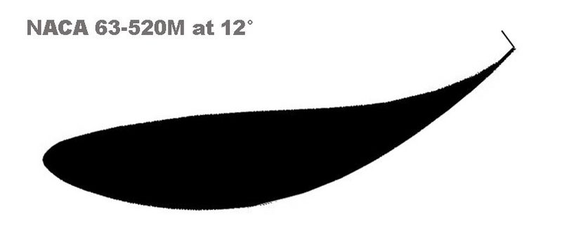
You're way over my head on this stuff, but these are some graphs from when I was getting some help on choosing a profile.
The profile is a modified (for camber) version of NACA 63-520, with a half-inch Gurney flap.
You're way over my head on this stuff, but these are some graphs from when I was getting some help on choosing a profile.
Reply
0
0
Using a stock head light motor you only have two positions out of the four :higher drag, braking, low drag, and the position you would use for a static. We chose to use it for where we would have it for a static wing and braking for the sake of simplicity for this first test.
I could easily adjust the rod down some to where it would be going between a low drag angle and higher drag for turns. The switch could be moved to the steering wheel on a button to actuate it, but this would now make it an active system that my drivers would need to pay attention to. I'm hesitant to add yet another thing to pay attention to in an endurance race.
You are understanding that correctly. To be fair though, to make the Arduino Board work, you will also need a GPS antenna and steering angle sensor, so the whole setup is more than just the cost of the board itself.
Reply
0
0
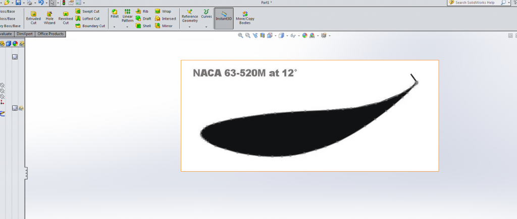
someone can overlay that profile view in solidworks create the airfoil and run a CFD for a quick comparison.
Does your equation take into account the gurney flap?
Reply
0
0
Newb
Joined: Jul 2014
Posts: 20
Total Cats: 3
And while I've got a smart guy's ear, what's the correct way to measure wing angle with an airfoil that's been modified for increased camber. Is it still a line from foremost to aftmost points, even if that seems at odds with the bulk of the airfoil?
Reply
0
0
Junior Member
Joined: Aug 2013
Posts: 180
Total Cats: -29
So... worth it, or wasted effort?
And while I've got a smart guy's ear, what's the correct way to measure wing angle with an airfoil that's been modified for increased camber. Is it still a line from foremost to aftmost points, even if that seems at odds with the bulk of the airfoil?
And while I've got a smart guy's ear, what's the correct way to measure wing angle with an airfoil that's been modified for increased camber. Is it still a line from foremost to aftmost points, even if that seems at odds with the bulk of the airfoil?
As for AoA, that's measured along the chord line straight from the leading edge to the trailing edge.
By the way, I'm not sure if you saw my edit earlier, but those original numbers were in newtons, not pounds force.
Reply
0
0
Newb
Joined: Jul 2014
Posts: 20
Total Cats: 3
In the land of the blind, the one-eyed man is at the top of the podium, even if he's Googling it.
I'm working on tenths, at this point. I've lined my wheel-wells, revised my splitter, covered more of the bottom of the car, put in this motorized wing-control contraption -- but took away enough weight to offset the new stuff. Hopefully, I'll at least be in the position of it not being worse...
I'd say I'll tell you how it works tomorrow, since I'm headed out to the track. But the forecast is NOT for a dry track. So we'll see.
Reply
0
0
I gave the CFD thing a whirl. Here's the results. The CFD was run at 120 mph with the airfoil you posted in the pic assuming the orientation of the AOA in the pic was correct.
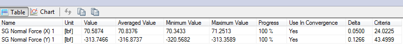
The results: 320 lb downforce and 71 lb drag @ 120 mph (somone with experience in this field please provide a sanity check on these results).
overlayed a spline and gurney flap per your picture and scaled to your measurements.
threw in some randomly shaped end plates.
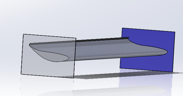
Maxed out my CPU for an hour to solve (course mesh size too)
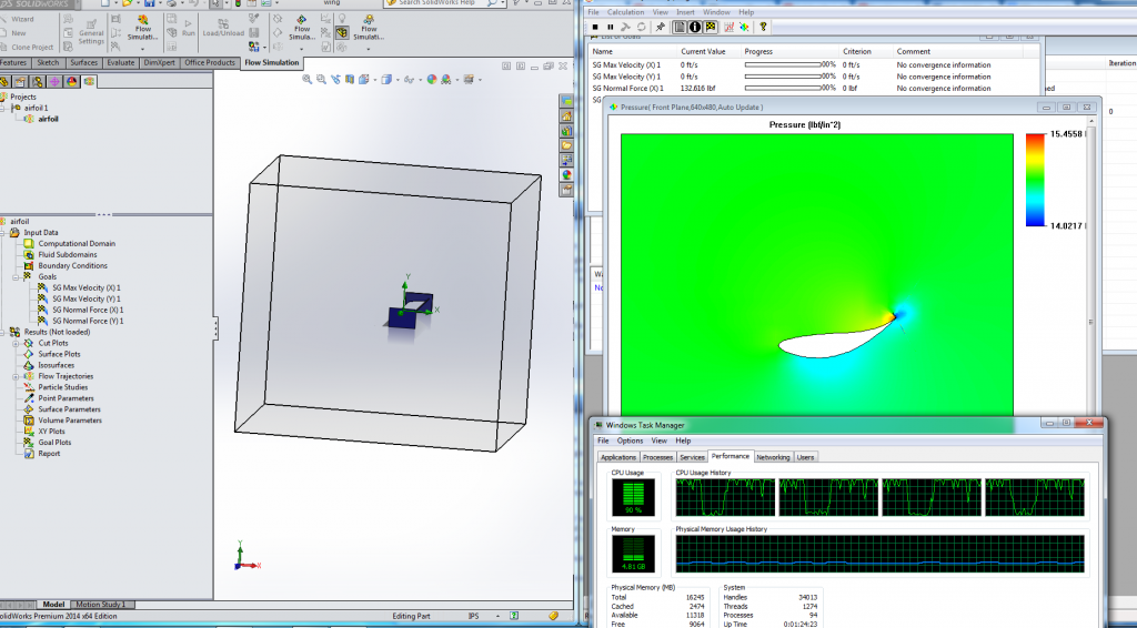
What you really care about (71 lb drag, 320 lb downforce)
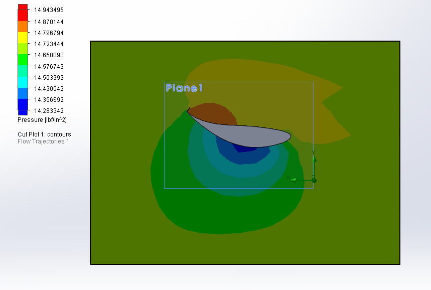
Pressure contour map at mid plane of wing
velocity contour map at mid plane of wing
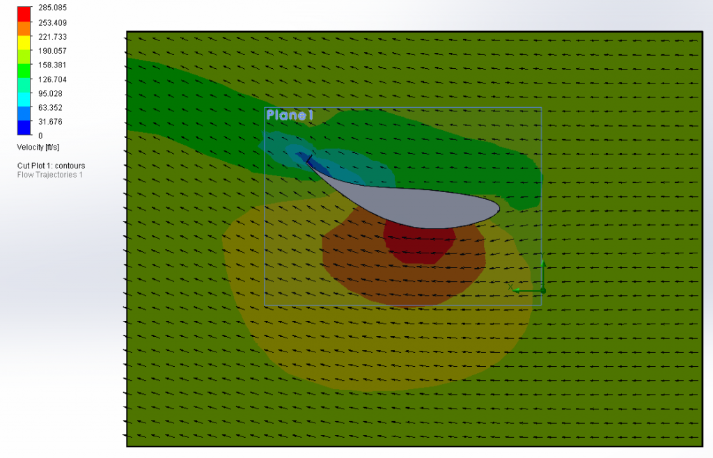
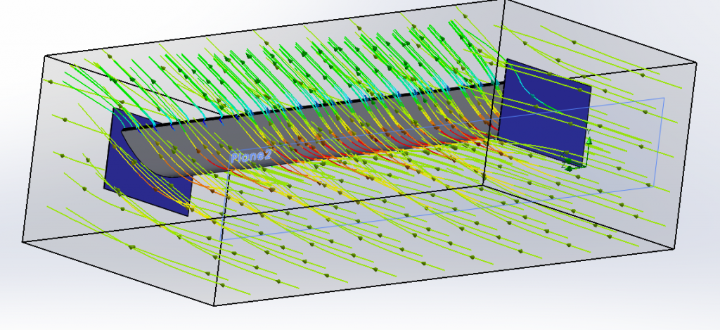
Velocity flow tragectory (top)
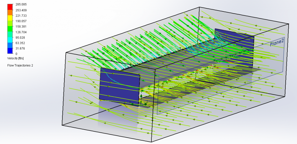
Velocity flow tragectory (bottom)
The results: 320 lb downforce and 71 lb drag @ 120 mph (somone with experience in this field please provide a sanity check on these results).
overlayed a spline and gurney flap per your picture and scaled to your measurements.
threw in some randomly shaped end plates.
Maxed out my CPU for an hour to solve (course mesh size too)
What you really care about (71 lb drag, 320 lb downforce)
Pressure contour map at mid plane of wing
velocity contour map at mid plane of wing
Velocity flow tragectory (top)
Velocity flow tragectory (bottom)
Reply
0
0

For something like this I just do a 2d solve for an area thats is a convenient multiple of with wing length and multiply but the length of the wing and assume its going to be a little big higher lift and lower drag than if I spent hours waiting for a 3d solve. For my wing to get accuracy in the slot I've got to be damn fine mesh, which means 10 minutes to 2d solve or go to bed for a 3d solution.
Reply
0
0
Junior Member
Joined: Aug 2013
Posts: 180
Total Cats: -29
Well damn, now I wish I hadn't corrected myself earlier. I could have claimed to be able to do CFD calculations with nothing but a pen, paper, and an XFOIL analysis.
On topic, can you do this again at 0* AoA and post results for comparison?
On topic, can you do this again at 0* AoA and post results for comparison?
Reply
0
0
For something like this I just do a 2d solve for an area thats is a convenient multiple of with wing length and multiply but the length of the wing and assume its going to be a little big higher lift and lower drag than if I spent hours waiting for a 3d solve. For my wing to get accuracy in the slot I've got to be damn fine mesh, which means 10 minutes to 2d solve or go to bed for a 3d solution.
Reply
0
0
Junior Member
Joined: Aug 2013
Posts: 180
Total Cats: -29
For the time being, I'm just going to consider the whole matter of endplates black magic and leave it to you and your CFD wizardry.
Reply
0
0
Even without the issue of the gurney flap, my method doesn't consider the effects of what's going on at the wing tips. It doesn't seem like too bad of an issue for DIY aircraft hobbyists, but it is for us since we're so limited on span and have to make up that surface area with more chord. Lower aspect ratios mean that wingtip vortices affect a greater percentage of the wing, so endplate design has a huge effect here and that's an area I've found almost no reading material on. I don't even know if the effect of endplates varies with AOA or not.
For the time being, I'm just going to consider the whole matter of endplates black magic and leave it to you and your CFD wizardry.
For the time being, I'm just going to consider the whole matter of endplates black magic and leave it to you and your CFD wizardry.
Reply
0
0

Reply
0
0


