custom gauge set up


I know this isn't really Race Prep but it's the only custom gauge set up thread that search found.
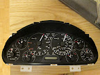
Here's mine, almost ready to install. This is the proof of concept model to test out back lighting, pointer lighting, gauge function and reliability. I have yet to get a WB bung welded in or a location to mount the oil temp sensor.
Anybody have a suggestion on the easiest place to mount an oil temp sensor on a 2000? Note that I'm using the 99/00 water temp sensor for oil to match with the gauge.
Adds Oil Temp, AFR and Boost Gauges plus Knock, Oil Press and WI lights.
Details:
Oil and water temp gauges - linear modified
Oil Pressure gauge - stripped, grease removed and rewound
Oil pressure sensor - VDO 0-80psi sender plus idiot light
AFR - Analog AEM
Boost - stripped Autometer
Check Engine, Seatbelt, Brake etc Lights - All LED
Backlighting - LED, dimmable
Gauge pointer lighting - LED, colour change on warn for tach, temps, oil, AFR and fuel.
Picasa Pic
Reply
 0
0

0

Sorry, not yet - I'm kinda embarrassed at the wiring spaghetti in there, not my usual work.
Thanks for your comments. I toyed with a few orientations of the tach and speedo. To get as much room as possible for the other gauges I moved them both upwards and closer together in the cluster; the needles can't go closer to vertical without hitting the gauge surround bezel or cutting the needles. Starting from 6:00 means they would move past vertical in their travel. Now it's mostly assembled I can see there might be room to move them down giving more options for needle position.
Yikes, it's home made. I bought a couple of used clusters for a total of $75 so I didn't have to rip into mine. There's probably $20 worth of wires, LEDS and such and I likely ripped through 25 sheets of laser printable acetate (at a buck a sheet). The boost gauge was donated by a friend and I bought the AEM W/B new.
It's pretty sweet that you have all that integrated into a stock cluster, but a minor point of weirdness IMO is how you have the tach and speedo dials clocked. For example, why not put the tach redline at 12:00, or 6:00 since you seem to like stuff pointing downward most of the time? If you're going to rotate them at all, I would configure them so "vertical" relates to some commonly used or important value, to make it easier for your brain to process when you're at speed. Just personal preference of course.
Yikes, it's home made. I bought a couple of used clusters for a total of $75 so I didn't have to rip into mine. There's probably $20 worth of wires, LEDS and such and I likely ripped through 25 sheets of laser printable acetate (at a buck a sheet). The boost gauge was donated by a friend and I bought the AEM W/B new.
Reply
0
0
Yikes, it's home made. I bought a couple of used clusters for a total of $75 so I didn't have to rip into mine. There's probably $20 worth of wires, LEDS and such and I likely ripped through 25 sheets of laser printable acetate (at a buck a sheet). The boost gauge was donated by a friend and I bought the AEM W/B new.

Reply
0
0


I know this isn't really Race Prep but it's the only custom gauge set up thread that search found.
Here's mine, almost ready to install. This is the proof of concept model to test out back lighting, pointer lighting, gauge function and reliability. I have yet to get a WB bung welded in or a location to mount the oil temp sensor.
Anybody have a suggestion on the easiest place to mount an oil temp sensor on a 2000? Note that I'm using the 99/00 water temp sensor for oil to match with the gauge.
Adds Oil Temp, AFR and Boost Gauges plus Knock, Oil Press and WI lights.
Details:
Oil and water temp gauges - linear modified
Oil Pressure gauge - stripped, grease removed and rewound
Oil pressure sensor - VDO 0-80psi sender plus idiot light
AFR - Analog AEM
Boost - stripped Autometer
Check Engine, Seatbelt, Brake etc Lights - All LED
Backlighting - LED, dimmable
Gauge pointer lighting - LED, colour change on warn for tach, temps, oil, AFR and fuel.
Picasa Pic
This is the most ridiculously awesome analog gauge cluster I have ever seen.
Reply
0
0

Senior Member
Joined: Aug 2010
Posts: 498
Total Cats: 0
From: San Luis Obispo, CA
I know this isn't really Race Prep but it's the only custom gauge set up thread that search found.
Here's mine, almost ready to install. This is the proof of concept model to test out back lighting, pointer lighting, gauge function and reliability. I have yet to get a WB bung welded in or a location to mount the oil temp sensor.
Anybody have a suggestion on the easiest place to mount an oil temp sensor on a 2000? Note that I'm using the 99/00 water temp sensor for oil to match with the gauge.
Adds Oil Temp, AFR and Boost Gauges plus Knock, Oil Press and WI lights.
Details:
Oil and water temp gauges - linear modified
Oil Pressure gauge - stripped, grease removed and rewound
Oil pressure sensor - VDO 0-80psi sender plus idiot light
AFR - Analog AEM
Boost - stripped Autometer
Check Engine, Seatbelt, Brake etc Lights - All LED
Backlighting - LED, dimmable
Gauge pointer lighting - LED, colour change on warn for tach, temps, oil, AFR and fuel.
Picasa Pic
Here's mine, almost ready to install. This is the proof of concept model to test out back lighting, pointer lighting, gauge function and reliability. I have yet to get a WB bung welded in or a location to mount the oil temp sensor.
Anybody have a suggestion on the easiest place to mount an oil temp sensor on a 2000? Note that I'm using the 99/00 water temp sensor for oil to match with the gauge.
Adds Oil Temp, AFR and Boost Gauges plus Knock, Oil Press and WI lights.
Details:
Oil and water temp gauges - linear modified
Oil Pressure gauge - stripped, grease removed and rewound
Oil pressure sensor - VDO 0-80psi sender plus idiot light
AFR - Analog AEM
Boost - stripped Autometer
Check Engine, Seatbelt, Brake etc Lights - All LED
Backlighting - LED, dimmable
Gauge pointer lighting - LED, colour change on warn for tach, temps, oil, AFR and fuel.
Picasa Pic
Reply
0
0
C
Reply
0
0
Don't be shy! I've modded a few clusters and they all look great on the outside and messy on the inside. Here's my Miata cluster - now it's your turn.
C
C
I've seen your work before Chris. In fact, it was your posts here at MT that prompted me to get off my a$$ and do something.
The electrical part is pretty simple if you can solder. I left the circuit panel in place so I could use the stock connectors which also gave me a place to connect my wires to run to the repositioned gauges. The LEDs are done the same way. One of my problems was using a US spec cluster for my Canadian spec car - until I realised the DRL connection was messing me up. The only other problem was using LED for the airbag and brake indicators; LED don't draw enough current to trip the electronics in the car so I added a resistor load to fix that.
Reply
0
0
Thanks for the pics! How's the backlighting handled? Looks like you've got a piece of clear plexi in there, and some sort of liquid mask.What program did you use to generate the faceplate, and what kind of printer was used?
C
C
Reply
0
0
The faceplate was made using Adobe Illustrator using the methods detailed at revlimiter.net. The (orange) liquid mask you refer to is simply permanent marker applied to both sides of a piece of clear acetate (both sides to improve colour density). The faceplate consists of three layers. The viewed layer is laser printable clear acetate, the middle layer is white paper and the bottom layer is the clear acetate with orange marker. The blue and red markings are just more marker on the paper layer.
The printer used was a HP1012, plain old black and white. I could not find any acetate bigger than letter size (legal would have been perfect) so there is a join in the visible layer. between tach and speedo Further, the feed accuracy of the printer means that paper and acetate do not exactly scale leading to a second join (near the boost gauge) to get paper and acetate to align.
Reply
0
0
Also, I managed to drop the vac/boost gauge one too many times during the build and it no longer zeros (it only travels between -20 and -10). I've tried resetting the needle and tweaking the bourdon tube to no avail. So its off to the local tuning shop for a replacement.
Once it's installed I'll post up pics. I still don't think I'll be making them to sell though - it's a whole crap load of labour.
Reply
0
0


My gauge setup is no longer being done because I got this...
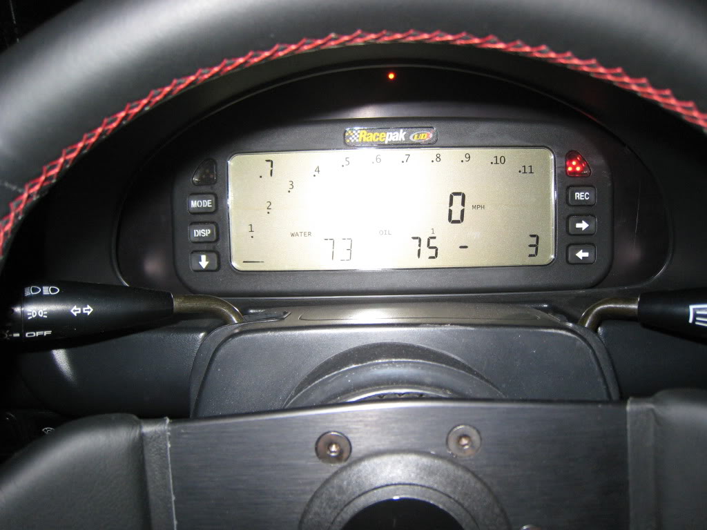
Monitors oil temp, water temp, oil pressure, RPM, ODO, trip meter and speed. Top left is boost right now as well, but when I go Rotrex since it's a 0-5v signal I'm going to trick it into reading my wb02. All I have to do is hook the dash up to my computer and change the calibration settings.
booya.
They're under $1000 too... I love this thing.
Reply
0
0

Newb
Joined: Mar 2010
Posts: 13
Total Cats: 0
In general you shouldn't solder automotive wiring. Soldering creates a stress point in the wire that is more likely to fail than if you had just crimped it.
So yes, your joint is solid, but that's exactly why it is more likely to fail.
Practice:
I have seen both crimp and solder joints fail in aftermarket engine management installs. For crimps they were loose and not checked well initially. For solder joints the wire cracked after a while at the point where the solder made the wire stiff.
Reply
0
0

When you do what wayne says the crimp is bearing the load, the solder is only a backup and insurance for the electrical connection. the shrink tubing also helps bear some of the load. It is probably the best way to splice.
Reply
0
0
Newb
Joined: Mar 2010
Posts: 13
Total Cats: 0
If you solder the crimp is irrelevant. With solder it will break at the edge of the solder where the wire goes from being stranded (non-soldered) to solid (soldered), because you have introduced a stress riser at that point. This is an inevitable fact of soldering.
If the wire doesn't ever see flex around the joint you can probably get away with it, but it's still not as good as a simple crimp (mechanically). This is why companies like Motec say in their manuals not to use solder, and why you'll rarely find solder in a factory loom.
If the wire doesn't ever see flex around the joint you can probably get away with it, but it's still not as good as a simple crimp (mechanically). This is why companies like Motec say in their manuals not to use solder, and why you'll rarely find solder in a factory loom.
Reply
0
0