
New FP miata
 08-08-2014, 10:44 AM
#181

What are you using for loads in your analysis?
And:
Can we see a picture of your front lowers before and after failure? And a picture of your rear uppers? I think I'm understanding you correctly, but not 100% certain.
And:
Rear upper arm solution we did.
Cut the arm. Welded .50" steel "caps" on both halves then drilled and tapped for threaded rod with a hex center. Kinda ugly, but effective and practically free.
Not so much luck with the front lowers we made from 1.5x.120 that didn't make it two runs on 12" slicks. Upper fronts we made are holding fine, but of course the uppers don't see the load the lowers do.

Reply
 0
0

0
 08-08-2014, 11:05 AM
#184
I calculated the the vertical load on the ball joint due to the corner load (from the spring resisting the roll) and the bump. What I didnt take into account was that the ball joint is actually angled and not vertical, but I didnt account for the the axial load added to the bearing from the lateral turning forces so it should work out about the same in the end. I ignored the radial load since the axial is much more important in this location.
Reply
0
0
08-08-2014, 11:21 AM
#185
Elite Member
iTrader: (8)

Join Date: Dec 2008
Location: Kingston, Ontario
Posts: 2,910
Total Cats: 51
Not to dull your CAD work, but being that the joint is at an angle, a good part of the loading will become radial which allows to handle a lot more load in the joint.
you analysis seems skewed in this case. sorry brah.
you analysis seems skewed in this case. sorry brah.
Reply
0
0
08-08-2014, 11:28 AM
#186
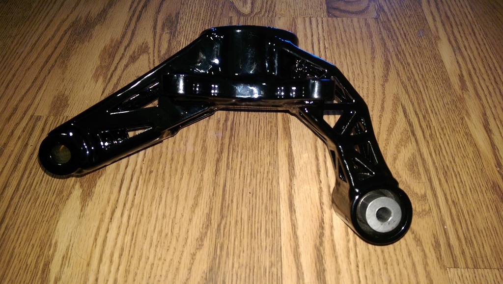
But this whole angled LBJ discussion brings up another point. The rod end based arms that the OP posted dont have the LBJ rod end angled like the stock arms, so they're going to be very droop travel limited and will be putting all the load axially like I calculated.
Reply
0
0
09-02-2014, 01:32 AM
#187
Senior Member
Thread Starter
iTrader: (2)

Join Date: Jan 2010
Location: Denver
Posts: 904
Total Cats: 14
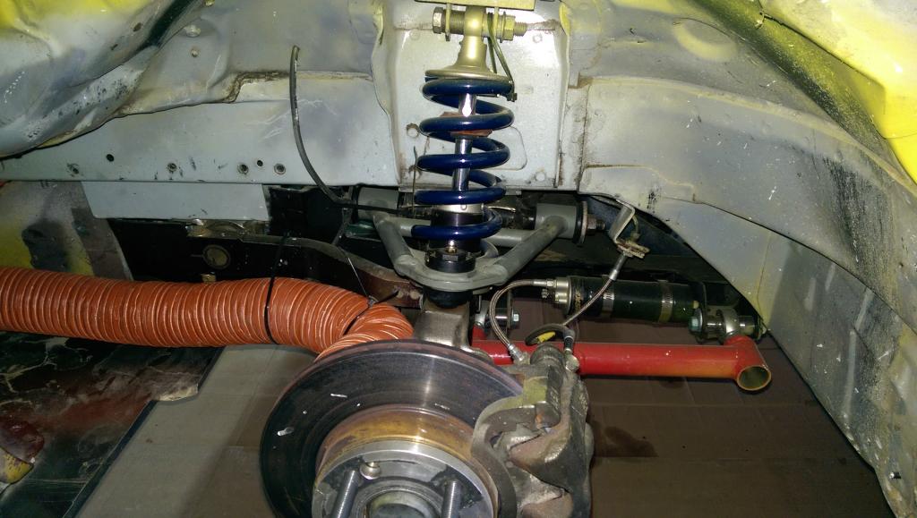
One month until I leave for the Runoffs at Laguna Seca, looking forward to driving this track as it is on my bucket list. Have been working my tail off on the car, and have all the crash damage repaired from last years shunt with the tire wall on the outside of Canada Corner. The new control arms are on the car as well, and I have a nice set of stock spares with new derlin bushings. I will be finishing the body tomorrow and plan on corner weighting and aligning the car on Wednesday and testing sometime next week.
It is a smallish field for this years championship not many guys from east of the Mississippi are making the tow all the way to the west coast. But there are some heavy hitters that will be in the field, it should be a great week!
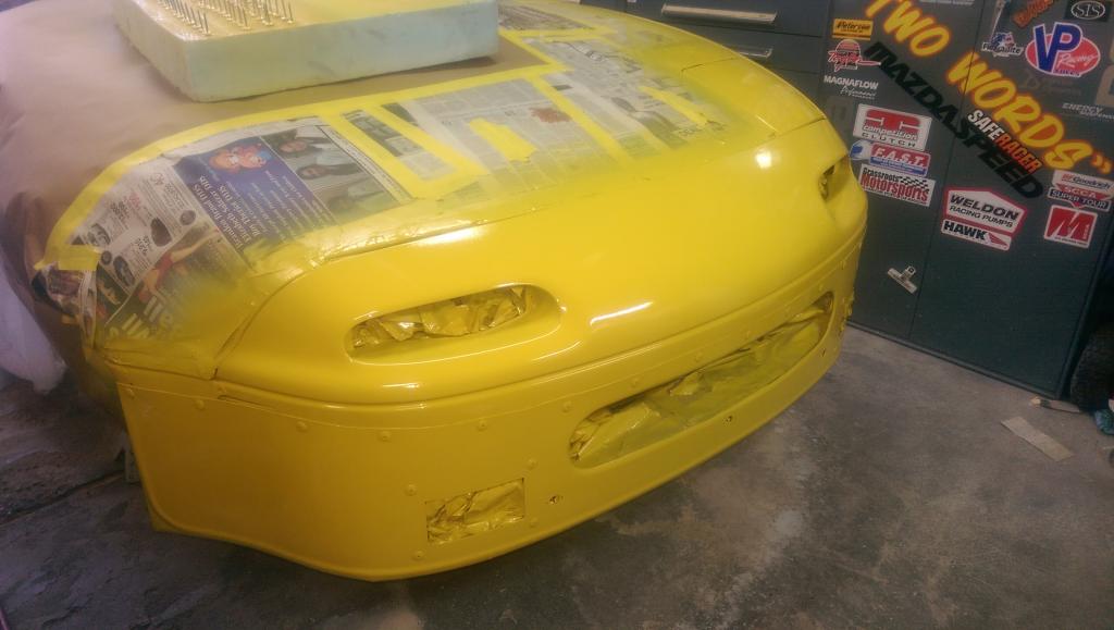
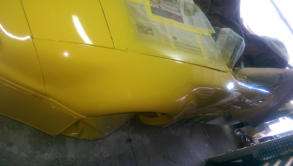
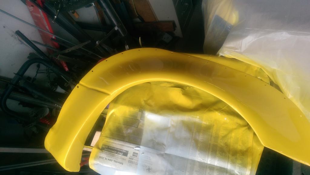
I included a few pics of my recent efforts. Looking forward to getting back in the car to test next week!!!
Since my last race at the end of May I have replaced the front sub frame, added new front control arms, laid up a new air dam, repaired the damage to the hood, replaced the drivers door, and front fender, repaired the rear flare and painted all the new and repaired parts. Time goes fast when your car is apart, hopefully, all the hard work pays off and the car will work well, and look decent.
[IMG]httpi408.photobucket.com/albums/pp170/hingstonwm/fp%20miata/IMAG1269_zpse30fa952.jpg[/IMG]
It is a smallish field for this years championship not many guys from east of the Mississippi are making the tow all the way to the west coast. But there are some heavy hitters that will be in the field, it should be a great week!
I included a few pics of my recent efforts. Looking forward to getting back in the car to test next week!!!
Since my last race at the end of May I have replaced the front sub frame, added new front control arms, laid up a new air dam, repaired the damage to the hood, replaced the drivers door, and front fender, repaired the rear flare and painted all the new and repaired parts. Time goes fast when your car is apart, hopefully, all the hard work pays off and the car will work well, and look decent.

[IMG]httpi408.photobucket.com/albums/pp170/hingstonwm/fp%20miata/IMAG1269_zpse30fa952.jpg[/IMG]


Reply
0
0
09-02-2014, 12:58 PM
#189
Senior Member
Thread Starter
iTrader: (2)
Join Date: Jan 2010
Location: Denver
Posts: 904
Total Cats: 14
Wish I could take credit, I found a guy who makes them, Can't remember his name right now. The part was cheap enough, just a touch over $200 but shipping was another 200. So the first thing I did when I received the part was to make a mold so I can build my own. I make mine a little more flexible than the original, using 4 layers of 6# woven mat. The underside has a lip that I use as a mounting point for the aluminum under tray, it extends to the front wheel arch and is attached to the stock under tray, giving the bottom of the car a smooth surface to the front wheel openings.
Reply
0
0


 10-14-2014, 10:39 AM
#193
Senior Member
Thread Starter
iTrader: (2)
Join Date: Jan 2010
Location: Denver
Posts: 904
Total Cats: 14
Taken out in turn 2 of the the first lap. I had a good start but didn't want to force the issue in the first real corner of the first lap, wish a couple of my competitors had chosen to show the same restraint. You can't win a race in the first corner, but you can certainly loose it and ruin others race at the same time. Had qualified 5th, both the car and I had more left, I felt comfortable and knew that I was fast enough to compete for the podium. Left side of car is completely tore up and is going to need a tug from a frame machine as well.
Last edited by hingstonwm; 10-15-2014 at 10:21 AM.
Reply
0
0
03-26-2015, 03:45 AM
#194
Senior Member
Thread Starter
iTrader: (2)
Join Date: Jan 2010
Location: Denver
Posts: 904
Total Cats: 14
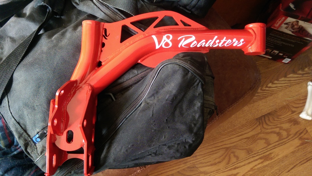
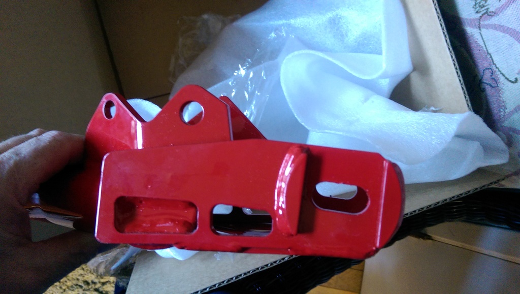
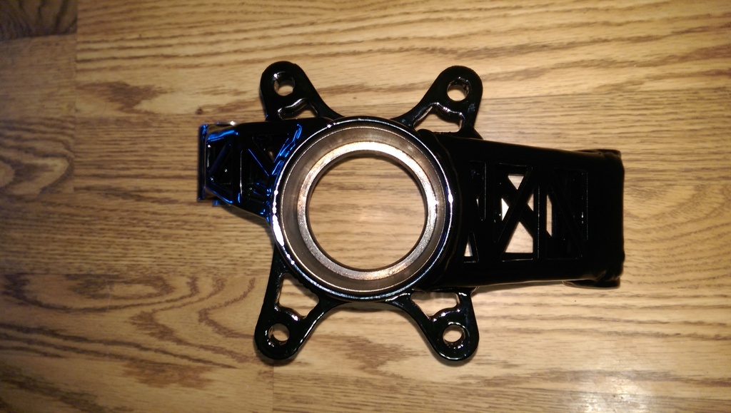
Runoffs damage is repaired, just need to get some paint on it. Making some huge changes to the car this off season, new shock package, going with a complete v8 roadster control arm set, drop uprights on the rear, and a fresh engine with newly allowed forged rods.


Reply
0
0
 04-20-2015, 10:08 AM
#199

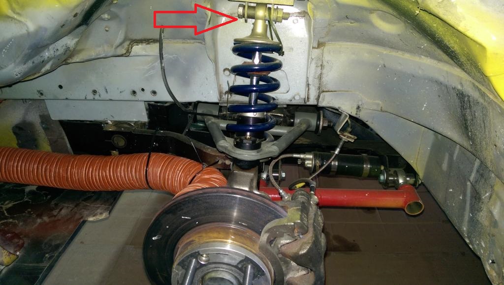
Can you give some insight into how you designed your shock perches? Where I am located we have tons of circle track guys and they are always upgrading their suspension, so I can get some decent used stuff for cheap, but I have yet to figure out a mounting solution. This plate you have made looks perfect. Very cool build. I really like watching your videos.
Reply
0
0
04-22-2015, 09:11 PM
#200
Senior Member
Thread Starter
iTrader: (2)
Join Date: Jan 2010
Location: Denver
Posts: 904
Total Cats: 14
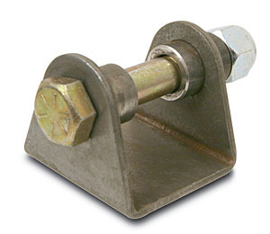
That is a standard circle track piece. 1/2 inch eye shock mount. It has a solid mounted spacer on one side and a floating spacer on the other side that is compressed into the shock by the mounting bolt. The mounting plate that it is welded to is just 3/16" flat bar cut into the shape of a top hat.

Last edited by hingstonwm; 04-22-2015 at 09:42 PM.
Reply
1
1


