When you click on links to various merchants on this site and make a purchase, this can result in this site earning a commission. Affiliate programs and affiliations include, but are not limited to, the eBay Partner Network.
Hi there, after searching for quite a long time I bought my self a ms2diy solderd it to the configuration folowing the ms2extra guide but read a lot about opto isolators, [img]blob:file:///2bc130e7-d281-4d63-91a9-cd25715e802f[/img]alternator regulators, and more. This is where I am now:
what are the mods i need to do for a stand alone solution? I am not new to electronics but i do not know where to start modding for a 1.8 nb.
considering you populated the entire board, I would use the VR input for crank sensor, and the opt isolator circuit for cam in.
then you need to wire the outer LED circuits to spark out on the db37.
then your fan control out needs a circuit (middle led).
ill have to like markup your board to show it -- give me a few minutes.
remove the yellow wire.
remove the jumper from IGBTOUT to IGN
remove the jumper from TACHSELECT to OPTIN
remove the jumper from TSEL to OPTOUT
Remove the transistor on the middle LED, replace it with the one for Q4.
ADD Q2 and Q19.
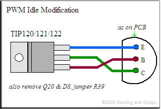
ADD the PWM idle Circuit.
Mount your TIP120 to the heatsink, using a mica insulator and thermal grease under the transistor.
Connect pin 1 of the transistor to pin 2 of Q4, pin 2 to pin 3 of Q4 and pin 3 of the transistor to pin 1 of Q4
Refer to the posted picture to check that your pins are all jumpered correctly
Do not install Q20, R39 or D8
Jump R39 with a wire
Solder the banded end of your diode to S12, and connect the other end to the middle leg of the transistor. You can use one of the spare 1N4001s from D1 or D2
A "better" spark circuit is this (black lines):
use pn2222222 transistors. Must use "HIGH spark out" in software.
I also saw i need to make a alternator circuit, and for the harness do i need to make any changes to this diagram? I have to connect iac1a for opto in, iac2a to clutch/ launch, iac1b to fan and iac2b to spark? for the wiring of the plug i used:
Did i forget anything or do i need to change more things?
I always recommend against installing ms2 on a 99 because you need to build many many many extra circuits to just get the minimum features.
here's what I would add:
two extra injector drivers to continue running sequential injection.
a/c input circuit
a/c compressor/fan output circuit
VICS output circuit
Alternator control circuit.
problem is, you cant fit all that inside the case/proto area and it's possible you cant even support that many inputs and outputs.... I would lose launch control to open up a spot for basic functions.
honestly, what I would do is return the ms2 cpu and case, and pick up a ms3 cpu, ms3x case, and ms3 expander board -- then follow MY writeup in my sig.
 12-13-2017, 03:42 AM


 0
0