When you click on links to various merchants on this site and make a purchase, this can result in this site earning a commission. Affiliate programs and affiliations include, but are not limited to, the eBay Partner Network.
Thought I would do a thread on a project I am just embarking on that may be vaguely interesting even to devotees of the turbo.
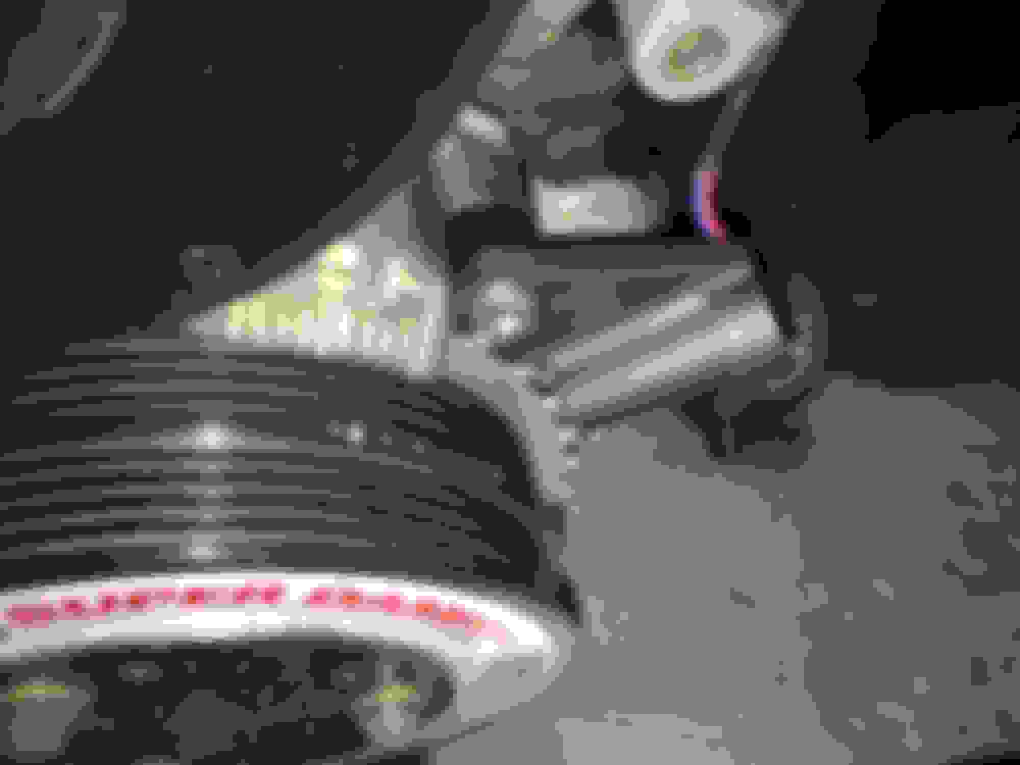
I managed to get my hands on this little beauty:
This is an OPCON Autorotor SR2 2087 twin screw / lysholm supercharger with a sandwich plate style laminova charge cooler.
It displaces 0.87L/rev, so about 53ci/rev. Max continuous rpm is 15000rpm. What little information I can find on this supercharger suggests it is good for 280 - 300hp.
The plan is to mount it coldside, with the supercharger / charge cooler mounted directly to a fabricated inlet manifold straight into the ports.
Everything inside the charger appears to be perfect so far, no wear on the housing or rotors.
The charge cooler is a lovely piece of engineering. It is an extruded profile with two laminova cores running inside. It contains all the proper ducting for the cores, really impressed with it.
Initial fit ups / measurements are going well. I was concerned the snout would be too long and push the charger too far back in the bay to be able to make a decent intake / throttle body assembly but it fits just right. The outlet of the charger is pretty much directly inline with port 2. The rear of the charger at this point is inline with the rear fuel rail bolt so a good bit of room there to bring the air round in a nice curve. The charge cooler is slightly forward biased for the sc pulley to be inline with the crank pulley, but only slightly and I am confident that I can fabricate a manifold that will have a good chance of having an even distribution of air between cylinders.
There will be some challenges. The clutch master needs to be moved as I am in the UK, so the car is RHD. Pretty sure I need to move the alternator to the other side of the engine to make way for the belt tensioner, but with those out the way there is actually a reasonable amount of room to allow me to make a decent intake manifold. Not exactly optimised runner lengths but I'm pretty sure low down torque is not going to be an issue! I think I can even package a bypass valve with it so I am happy with that.
I only really have two major concerns currently.
One is ensuring the sc / charge cooler assembly is properly supported. It is not a light unit, together weighing in at about 13.4kg dry. The plan is to make the intake manifold out of mild steel rather than aluminium. I am hoping the mild steel and welds will be more resistant to the vibrations the engine will transfer into what is essentially a 25cm arm with a big weight on the end than an equivalent manifold in ali. The required short runner length / compactness of the manifold should mean that any weight penalties due to material choice should be minimal. I think also a support coming up from the block to the supercharger to triangulate the assembly will also be required to minimise the risk of breaking the inlet manifold studs / cracking the head. I have seen the movement generated by the engine, particularly at idle on my current hotside setup on items mounted about this distance from the engine and it is quite brutal,so I need to ensure I over engineer it with a significant safety factor.
The other challenge is the lubrication of the charger itself. The drawings for it show ports in the gear case for engine oil at engine pressure, and a drain back to the sump. I would rather not share the oil with the engine for this. I am concerned about getting the hose sizing / restrictor set up to provide enough oil for the SC while not bleeding too much flow off and dropping the oil pressure too low in the engine. The engine is in good health with new bearings and oil pump with the stage 1 Boundary billet gears end of last year, but the ports on the sc are very big, G1/4!
If I go with a self contained system for the SC and use the specialised supercharger oil like the Eaton and current Kenne Bell units use then from my research the level of oil in the gear case has to be kept within quite tight tolerances to avoid disaster. Too little oil and the gears get too hot and eat themselves. Too much oil and it generates too much heat in the case, boils the oil and destroys the seals, coupler and gears. I am keen to avoid this as I have never seen another of these chargers about! There is also no dipstick or fill plug to show the correct level to fill to.
From my research I understand BEGI did a hotside setup with an Autorotor for the 1.6 donkeys years ago that required engine oil. I am hoping Corky will see this and be able to offer a little advise on oiling!
I have also tried reaching out to Kenne Bell for advise, no response yet but from their website they are on shutdown with Covid so I live in hope I get a response sometime
Anyway, progress will be a little slow, there is plenty to work out and I had to make a deal to decorate the house with the better half before I start this project, but I thought I would introduce it.
Really excited about the prospect of knocking on 300hp with a coldside supercharger!
Nice! I DIY'd a 2076 cold side as part of my compound prototype, it is a sweet charger. Make sure you run a bypass, they scream like a banshee off boost if you don't. I went A/A FMIC, which really projected the sound, the W/A will cut it down quite a bit I would think. Oversize the W/A, these create heat all the time, so you have to shed more.
You don't need to run motor oil from the engine, traditional SC oils can be used on a sealed case.
Compound? 😂 got a link to that build? No idea how you set that up, did the sc feed the turbo? Did you throttle the sc?
Definately will run bypass. The internal compression is 1.4, as you say always creating heat / boosting. Other side of it is less internal turbulence / heat than a roots with less rotor helix. There seems to be three ways to kill these, over rev, oil, or heat from no bypass. Also going to make sure it gets a proper cold air feed.
Its good to know there is some experience out there with these because info is a lot thinner on the ground than say Eaton stuff.
How did you decide / find out the oil fill level? Did you use a breather on the top to a catch can?
^You have some nice parts and an interesting project! Hopefully things will fit.
Just read through most of both of these. You are both crazy. Very impressive engineering both in terms of physical packaging and control systems.
That brazed aluminium joint was beautiful.
The alternator / heat issue is one I will have to think about. I will only have an exhaust manifold that side rather than manifold plus turbo but it isn't an aspect of the build that I had considered yet.
I run a 36-2 trigger wheel with an nb crank sensor, and had spotted the belt run issue when relocating the alternator. My thinking was incorporating an additional idler into the run to direct the belt away from there, but good to see another potential route around that issue.
It also got me thinking about what sensing I want to incorporate into the system.
I certainly have a lot less to worry about in terms of control systems but I enjoy regular track days, so I need to be able to keep an eye on temperatures.
Currently I am thinking charge cooler coolant temperature, just before it enters the laminova cores, and also supercharger oil temperature. I think there is going to be a bit of R&D in that so I need to keep an eye on it.
Undecided whether to use sensors wired into the ADC inputs on the Megasquirt or basic sender and gauge sensors. I am swayed more towards the ADC 0-5v sensors because of the logging functionality. For easy 'you need to come into the pits now' communication I will output a signal to an LED warning light.
I made the fixture so I could fabricate the inlet manifold between charge cooler and cylinder head. Very basic, two rails bolted to the bottom of the head with spacers in between to give a level plane and set the height of the sc relative to the head. I bolted the bottom of the charger to a thick plate, and bolted a straight edge to the front of the sc pulley. I lined up the forward / backward position, then squared it up by measuring the distance from the straight edge to either side of the machine parts on the front of the head by the cam housings. When it was all straight and correct I welded the sc mount plate to the fixture rails to set all the positions solidly.
Next was beginning to fabricate the manifold itself out of steel. First up the individual port runners. These needed to be formed into ovals to match the ports and this also required shrinking the circumference of the tube.
Did this by cutting triangular slots, forming with a vice, compressing the ends back together and welding up then grinding back to give the required shape.
Next step was to fabricate the common plenum area between runners and charge cooler. This was really just boxing in using the fixture to tack everything in the correct position before fully welding,
Really happy with how it came out. Checked alignment to the spare head and it was still bang on even after full welding. There is a little bowing in the charge cooler mount plate, about 0.5mm across the length. When I bolt it up to the charge cooler it does bring it all into line, but I will get my local machine shop to face it up anyway, I don't really want to be adding unnecessary stresses into the assembly.
Next up was the trial fitment on the engine. It went really well, nothing unexpected clashed. Fitment is tight but that was always to be expected.
And best of all it was all still bang in line measured with the straight edge of truth! I didn't take a pic of the bypass off the back of the inlet but that also fitted around everything it needed to.
The clutch master and res need to move so I started on my mechanism to move the cylinder inside the cabin. A couple of rod ends transfer the pedal motion to a lever fitted rearward on the stock pedal assy. The aftermarket cylinder mounted on the side of the pedal assy is then actuated via this rearward lever. All the motion ratios worked out, just need to beef up the top mount of the lever, it was all just bolted together with odd bolts to test the theory.
Bit of a whirlwind tour but that is where I am right now.
Thanks for the update, I have an old kennebell kit that uses an autorotor/lysholm. It’s currently on the shelf... What do you plan to do for the inlet throttle body?
Thanks for the update, I have an old kennebell kit that uses an autorotor/lysholm. It�s currently on the shelf... What do you plan to do for the inlet throttle body?
Oh cool, what is the setup on the Kenne Bell kit? Hotside / coldside / intercooled / size of sc? I had stumbled across mentions of the kit but never saw any photos.
Once the clutch and fuel reg are out the way it will be clear for a 90deg alloy pipe bend welded to a plate on the back of the charger. The other end of the pipe will be aimed up and over the coil packs. The tb I am going to use is for an upgraded Mitsubishi Evo. It is 70mm diameter and I will use the Evo TPS. I have made an adapter plate to run an NB IAC valve. The Evo IAC valve is a stepper type and pretty massive with the housing it lives in. This will then be ducted over the top of the coil packs to my current cold air box which takes a feed from the cowl area.
Oh cool, what is the setup on the Kenne Bell kit? Hotside / coldside / intercooled / size of sc? I had stumbled across mentions of the kit but never saw any photos.
It's on the hotside. It doesn't come with an intercooler at 6-7 psi, but it really needs one as IATs are really high. An air to water was offered as an upgrade, but I made my own front mount air to air (18*21*3in I think). It's a .87 liter sc.
Originally Posted by Tchaps
the clutch and fuel reg are out the way it will be clear for a 90deg alloy pipe bend welded to a plate on the back of the charger. The other end of the pipe will be aimed up and over the coil packs. The tb I am going to use is for an upgraded Mitsubishi Evo. It is 70mm diameter and I will use the Evo TPS. I have made an adapter plate to run an NB IAC valve. The Evo IAC valve is a stepper type and pretty massive with the housing it lives in. This will then be ducted over the top of the coil packs to my current cold air box which takes a feed from the cowl area.
This part is super important to make full use of the sc without having to overspin it. They are really sensitive to inlet restrictions size*length*path (and air temp). Whenever I get my kit back on, I plan to build a sheet metal inlet 180 and use an oem mustang gt500 throttle body. I may revise that to use the cowl air and just make it a 90* to an air box. With the left hand drive, the master cylinder is in the way.
I can't wait to hear how it sounds. Hopefully because of the bypass it will be relatively tame at ideal and cruise then unleash the banshee on acceleration but we shall see.
So speaking of inlets I started the fabrication this weekend. I cut the two flange plates then cut a 76mm diameter 90 deg ali pipe to suit were everything needed to be. It is very tight with the TPS only 5mm or so away from the firewall on one side, getting the IAC valve behind the chargecooler on the other and then aiming the tb inlet in the right direction. Took my time and it looks to have a nice sweeping curve into the back of the charger. Due to the angle of the cut the pipe also covers most of the back of the sc inlet making good use of the space. First pic tacked up:
Test fitted
Next sorting out the bypass valve piping. This is where the bypass mounts on the inlet manifold with the silicone bend that ducts it back to the inlet. Close but it is clear of everything back there.
I then welded on a pipe to the back of the sc inlet to duct the recirculated air.
And now a view of the competed sc unit on the bench
And loosely bolted in the car again
This is all looking amazing. The thing I miss most from my JRSC setup is the sound. Not sure how these compare to the eaton superchargers, but with the bypass, the eaton was dead silent, even spinning it out to 17k rpm.
This is all looking amazing. The thing I miss most from my JRSC setup is the sound. Not sure how these compare to the eaton superchargers, but with the bypass, the eaton was dead silent, even spinning it out to 17k rpm.
Thanks very much. Not really sure how this is going to sound if I'm honest. I have seen a few old videos of VW Corrados with Autorotors and they were roudy to say the least, not sure if they used a bypass though.
Got some more progress. Alternator is halfway relocated. The main lower bracket is done and straight, although it may need some reinforcement, The top mount will be a tie rod / rose joints. I had to move the crank sensor also, as it would have fouled the new belt run. I moved it up to the next bolt hole up and spaced it back out to be in the correct position. My only concern is possible signal interference from the alternator. I don't have to worry about the crank / cam phasing as I only use crank signal, wasted spark.
I also fitted the modified clutch pedal I made, that moves the master cylinder inside the cabin and the reservoir out of the engine bay.
It uses rod ends to actuate a lever further back that moves an aftermarket master cylinder of the same size as the stock cylinder.
Fitting it was a total PITA lying under the dash but it went in. Suprisingly the movement was all clear, I thought I was going to have to move the bunch of plugs you see in the photo below but they actually don't interfere.
Reservoir is now in the cowl area, it bolts through the cowl panel and a hose joins it to the cylinder. Where the res goes through the cowl I have used sealer to make sure water does not come into the cabin.
The pressure hose comes down from the cylinder, through a hole in the transmission tunnel through a grommet and to the slave cylinder.
Bled the system and it all feels normal. So clutch is now out the way of the supercharger inlet!
Charge cooler pre rad / res is almost done too now, updates will follow soon
Brake (aka clutch) fluid is hygroscopic, and the cowl is not the greatest place for that stuff. However, since the application doesn't impose the same demands on the fluid as the brakes - massive heat and pressure - it should be ok. It might result in accelerated corrosion in the m/c as a result of elevated moisture content, so watch for any leakage around the piston seal. No idea of the time scale for this though.
Been a while since I updated this but progress has been moving along nicely.
I made the belt tensioner. It is 10mm Ali plate, bolted to the front of the engine at the old alternator mount, the oil pump bolt just in from that and the water pump alternator tensioner ear. It is spaced out to the correct offset for the crank and supercharger pulleys. The tensioner itself is from a Jaguar XKR supercharged and the idler is from a Land Rover Discovery. They give me the capacity to run an 8 rib belt, which is what I am going to do.
4 rib belt on there just to check it all works
Next up the charge cooler system. The pump is mounted under the charger on a bracket to the front subframe. The red end caps on the inlet and outlet visible in the photo above. This is wired in using the old AC fan circuitry. The wire at the ECU will be wired in to the MS fuel pump pin, so it will prime and run with the fuel pump. Very cleverly I bought a radiator that was 15mm too wide to fit between the front chassis legs! So extensive surgery was required to shrink it down.
Just about fits. It is mounted on rubber isolators completely separately to the main coolant radiator to try to minimise heat transfer as much as possible.
This pic shows the radiator mounted, slightly offset to the left of pic to give room on the other side for the charge cooler pipe work to come past it back into the engine bay. There is the charge cooler reservoir that I made mounted just in front of the shock tower. The cap is only mm away from the bonnet to ensure the charge cooler is always full of coolant if the res is filled properly. It should also give a good pressure head for the pump which isn't mounted quite as low as I would like. The lines are all a -12.
I also mounted the LS style coils I got on the rear of the head where the stock coils live on what could loosely be described as a bracket. They are in solidly though and the wiring all fits underneath them now I have thinned it out a little.
I will take the edges off and paint before final install and give it some paint. I got some custom HT leads made to link it all together and they were only �40!
Air ducting is mocked up to link the tb with the airbox over the other side of the bay. Hopefully it will be ok flow wise, I will link my secondary pressure sensor to the sc inlet to make sure I am not seeing a pressure drop at higher rpms / throttle % and so losing power.
There has also been a change in direction in terms of the lubrication of the charger. I made contact with Dennis Priddle through AJ6 Engineering here in the UK. Dennis used to use Autorotor superchargers, amongst other brands on a variety of engines. He used to build and race dragsters / funny cars and is the first person outside the US to do a 6 second 1/4mile pass, and the second person from the UK to be inducted into the International Drag Racing Hall of Fame. Fair to say he knows what he is talking about when it comes to Autorotors. He gave me the specs to be able to check my rotor clearance, which was concerning me as I knew the charger had been rebuilt but not by who. They are perfectly in spec. Amongst other pointers he also told me that the size 2 superchargers like mine do not have a big enough gear casing to reliably run a self contained oil bath system, and strongly recommended the engine oil feed system that is on the drawings for the unit.
Previously I had been concerned about this method as I know people had issues with insufficient drainage and the gear case filling with oil. I think now this was due to running a 1mm restrictor rather than the 0.6mm that Dennis recommended, and the size that I will run. I am going to take the feed from the oil pressure sensor port and use a -4 line up to the -4 / 0.6mm restrictor I knocked up on top of the charger. I will bore out the drain on the gear case to 3/8" (before it was 1/4") and run a -10 drain line back to the sump to ensure there is plenty of drainage capacity. There will be a small breather (-4) from the nose of the charger back to the valve cover to promote oil mist flow into the nose bearings.
I have started work on the catch can / crankcase breathing but I will leave that for another day.
Enjoying watching this build.. I have thought sometimes I would go cold side if I did another one, seems simpler. Obviously from this thread there�s no �free lunch� tho.. Looks nice, so clean


 5
5


 but it was kinda fun too.