Rube Goldberg's Supercharger Setup
 02-21-2008, 01:05 PM
#21
I'm Miserable!

Join Date: Nov 2007
Location: Sweden
Posts: 67
Total Cats: 0
Flow = pressure / resistance
Resistance = viscosity*lenght/diameter^4
You have the same viscosity in the pipe, so scratch that.
two 2,5" pipes 2*2,5^4= 78.125
one 3" pipe 3^4= 81
You'll get away with a 3" pipe, and have some change left
Resistance = viscosity*lenght/diameter^4
You have the same viscosity in the pipe, so scratch that.
two 2,5" pipes 2*2,5^4= 78.125
one 3" pipe 3^4= 81
You'll get away with a 3" pipe, and have some change left

Reply
 0
0

0
02-21-2008, 03:34 PM
#22
Elite Member
Thread Starter
iTrader: (16)
Join Date: Aug 2007
Location: Houston, TX
Posts: 9,297
Total Cats: 477
Well I'll likely use aluminum charge pipes. I could make my own dual 2.5" to single 2.5" Y adapter. I have a friend who is a machinist and has a TIG welder, so he can weld up aluminum if I make the parts. Hmm, tim says use 2.5 and Niklas says Y it to one 3". I don't know what would be the best or if either would make a difference. If the measurable differences are insignificant, I'll just stick with 2.5" for everything, though I will probably use a 3" collector for the intake, 2.5 just seems too small. I know I couldn't get 4 large pipes in a 2.5" collector anyway. I may use the stock TB, or I may use the one that came off the millenia, as I think it's bigger.
Reply
0
0
02-21-2008, 05:01 PM
#23
I'm Miserable!
Join Date: Nov 2007
Location: Sweden
Posts: 67
Total Cats: 0
From what i can tell, a 2,5" pipe will more than fill your needs for 460 cfm.
http://www.pipeflowcalculations.com/flowrate/index.htm
Edit: the comparison i made was just to show that you would have more flow with a 3" pipe than with two 2,5" pipes
http://www.pipeflowcalculations.com/flowrate/index.htm
Edit: the comparison i made was just to show that you would have more flow with a 3" pipe than with two 2,5" pipes
Reply
0
0
02-21-2008, 09:59 PM
#24
Elite Member
Thread Starter
iTrader: (16)
Join Date: Aug 2007
Location: Houston, TX
Posts: 9,297
Total Cats: 477
Here's a couple pics of the Y coupler I would build to combine two 2.5" pipes into one 2.5" pipe. I would probably have both charge pipes go the the drivers side area in front of the radiator fans and turn down, then to the coupler, then one 2.5" pipe down to the intercooler.
http://i231.photobucket.com/albums/e...smx5/Ypipe.jpg
http://i231.photobucket.com/albums/e...mx5/Ypipe2.jpg
http://i231.photobucket.com/albums/e...smx5/Ypipe.jpg
http://i231.photobucket.com/albums/e...mx5/Ypipe2.jpg
Last edited by patsmx5; 02-21-2008 at 10:13 PM.
Reply
0
0
02-22-2008, 09:50 AM
#25
Elite Member

iTrader: (9)
Join Date: Jun 2006
Location: Chesterfield, NJ
Posts: 6,898
Total Cats: 399
That's fine. Keep in mind that the narrower the Y angle, the harder it is going to be for the welder to weld in between the Y. For Tig welding, you can only stick the electrode out so far before bad things start to happen. Not that big of a deal though, your welder friend should be fine.
Reply
0
0
02-22-2008, 10:36 AM
#26
Elite Member
Thread Starter
iTrader: (16)
Join Date: Aug 2007
Location: Houston, TX
Posts: 9,297
Total Cats: 477
Yea, I thought about that after I finished drawing it. I may change it to 15* angle if I need to, as that seems to be a common angle anyway.
So, about the intake manifold I want to build. It would basically look like a header, with large runners and a collector with a TB bolted to it. I'm wondering if I could get away with not building it equal length?
So, about the intake manifold I want to build. It would basically look like a header, with large runners and a collector with a TB bolted to it. I'm wondering if I could get away with not building it equal length?
Reply
0
0
02-22-2008, 10:44 AM
#27
I'm Miserable!
Join Date: Nov 2007
Location: Sweden
Posts: 67
Total Cats: 0
why would you like to build an intake of that type? just build a log type with runners, seems easier, and sure is more effective.
log as in reducing area log
edit: didn't think right, coldside is was...
but i still think it would be best with a log type, equal lenght runners, just curved up, so that the intake-log sits next to the cold side.
log as in reducing area log
edit: didn't think right, coldside is was...
but i still think it would be best with a log type, equal lenght runners, just curved up, so that the intake-log sits next to the cold side.
Reply
0
0
02-23-2008, 01:17 AM
#28
Elite Member
Thread Starter
iTrader: (16)
Join Date: Aug 2007
Location: Houston, TX
Posts: 9,297
Total Cats: 477
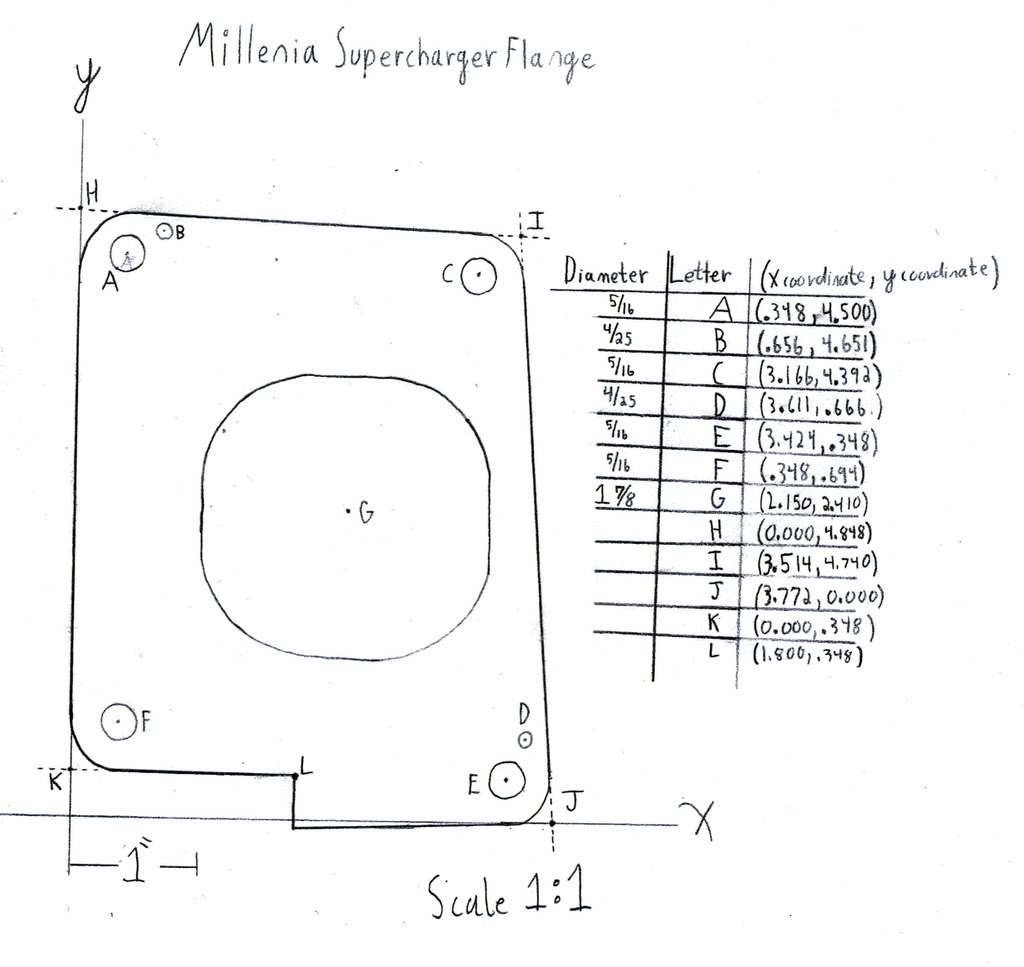
I spent wayyy too much time doing it, but I now have a blueprint for the SC flange. It would seem simple, probably just a rectangle, four bolt holes, and a circle for the air to go through. Wrong. No two sides are parallel or perpendicular, all the bolt holes are in diff spots, no two lying in the same X or Y coordinate. Actually, the two left bolts share a X coordinate, but that's it. I had to use a caliper and Law of cosines to do all this. It sucked, but now it's done and I have a blueprint that's very accurate.
This is just a 1:1 scale pic of the flange. It doesn't have any specs in it yet, I'm still working on making the final print, I have 4 pages with numbers on them to put together to make the final print.
Edit: got the final print finished:
This is just a 1:1 scale pic of the flange. It doesn't have any specs in it yet, I'm still working on making the final print, I have 4 pages with numbers on them to put together to make the final print.
Edit: got the final print finished:
Last edited by patsmx5; 02-23-2008 at 02:27 AM.
Reply
0
0
 02-23-2008, 06:12 AM
#31
Senior Member

Join Date: Mar 2006
Posts: 1,380
Total Cats: 2
I need some advice on the intake manifold and charge pipe design. The SC's have a 2.5" outlet on top. I'm not sure but I was figuring on having the two pipes join and go into an intercooler, then out and to the intake. Problem is the pipes for the oultets are 2.5" To join them both into one large pipe I would need a 3.5" pipe to keep the area about the same.
Pipe Size /Area
2.5 /4.9
3 /7.1
3.5 /9.6
So what should I do here, use 3.5" charge pipes? I could say let them combine into a 3.5", then taper it down to 3" and buy an IC with 3" inlets and outlets. I doubt Ebay has IC's with 3.5" Outlets.
Also since I'm building a custom intake manifold anyway, I could make the collector for the intake say 3" or 3.5, but would need a really big TB, and that would make it touchy.
Ideas are welcome.
Mark
Reply
0
0
02-23-2008, 08:29 PM
#32
Elite Member
Thread Starter
iTrader: (16)
Join Date: Aug 2007
Location: Houston, TX
Posts: 9,297
Total Cats: 477
^^^ Makes sense, that's how a lot of the OEM stuff on the millenia was, really small pipes. I'll just you both 2.5" pipes into 1 and buy a 2.5" IC and charge pipes, as they are plentiful on eBay.
I'm not sure how the intake is going to be done yet. I know it would be better to keep the SC close to the engine. The close it is, the more rigidly it will be mounted. I was thinking of something like have the SC close to the motor, and the intake below it. Is it common knowledge that a log manifold has X, Y, and Z benifits over say a 4:1 colector style? I just thought it might be easier, but if a log type will fit, I'll do that.
I'm not sure how the intake is going to be done yet. I know it would be better to keep the SC close to the engine. The close it is, the more rigidly it will be mounted. I was thinking of something like have the SC close to the motor, and the intake below it. Is it common knowledge that a log manifold has X, Y, and Z benifits over say a 4:1 colector style? I just thought it might be easier, but if a log type will fit, I'll do that.
Reply
0
0
02-24-2008, 05:28 PM
#33
Elite Member
Thread Starter
iTrader: (16)
Join Date: Aug 2007
Location: Houston, TX
Posts: 9,297
Total Cats: 477
I'm wondering how I should go about doing all this. I will need to tap the oil pan on both sides for oil returns, as the SC's require oil feed just like a turbo. I would feel much better pulling the pan to do it as I don't want metal shavings in my oilpan. I understand to get the oilpan off it's drop the subframe or pull the motor. I have a new clutch/flywheel to put in and I'd like to do motor mounts too, so looks like pulling the engine is the thing to do, and do everything at once while it's easy. Probably do a coolant reroute too while it's out. Anything else to do while the engine is out?
I may try to fabricate all the SC hardware with the engine out. Should be much easier to work on hanging on a lift then cramped in my engine bay. However, I'd have to be damn sure I build it so that it will fit when it's put in the car. I'm thinking I'll take a lot of measurements from various points of the engine to the car so I can make sure my hardware stays confined to those points. Sound like a plan?
I may try to fabricate all the SC hardware with the engine out. Should be much easier to work on hanging on a lift then cramped in my engine bay. However, I'd have to be damn sure I build it so that it will fit when it's put in the car. I'm thinking I'll take a lot of measurements from various points of the engine to the car so I can make sure my hardware stays confined to those points. Sound like a plan?
Reply
0
0
 02-25-2008, 12:21 AM
#35

nah **** that Man just do a outline with a grease pencil or tap it where i tapped mine just by the motor mount there is no AC there. Tapping in the front of the pan makes no real sense to me unless it is your only option. With the exhaust etc of, and a 90 degree air grinder etc it is easy to tap in the middle.
Reply
0
0
02-25-2008, 02:32 AM
#36
Elite Member
Thread Starter
iTrader: (16)
Join Date: Aug 2007
Location: Houston, TX
Posts: 9,297
Total Cats: 477
I talked to another member who said he greased the bit, had air pressure blowing through the valve cover so air was blowing out where he drilled and taped. He used grease on the bit. He was careful not to get metal in it. When done, he flushed it 3 times with mineral spirits. The next day he pulled the pan and it was full of metal. I do not want metal shavings in my motor, so the pan's coming off.
Reply
1
1
02-25-2008, 09:36 AM
#37
Read up on the crazy power this thing putting out. Maybe an idea.
http://www.musclemustangfastfords.co...bra/index.html
http://www.musclemustangfastfords.co...bra/index.html
Reply
0
0
02-25-2008, 06:06 PM
#38
I talked to another member who said he greased the bit, had air pressure blowing through the valve cover so air was blowing out where he drilled and taped. He used grease on the bit. He was careful not to get metal in it. When done, he flushed it 3 times with mineral spirits. The next day he pulled the pan and it was full of metal. I do not want metal shavings in my motor, so the pan's coming off.
Reply
0
0
02-25-2008, 06:13 PM
#39
Elite Member
Thread Starter
iTrader: (16)
Join Date: Aug 2007
Location: Houston, TX
Posts: 9,297
Total Cats: 477
Well, I don't like the idea of metal shavings in the pan, plus it's possible for them to accumulate over the pickup tube and stick to it, causing oil starvation. I couldn't make my self do it KNOWING there's metal bits and shavings in the pan that potentially could ruin my motor. Plus I have to tap it twice, once on each side, and I'm not even sure I could do it on the passengers side, andI would be more likely to end up leaving metal in it.
Reply
0
0
03-01-2008, 12:51 AM
#40
Elite Member
Thread Starter
iTrader: (16)
Join Date: Aug 2007
Location: Houston, TX
Posts: 9,297
Total Cats: 477
Right now the plan is to weld the hotside brackets to the header flange for strength and rigidity. It will also be braced off the header tubes, as well as off the cast iron bracket the A/C compressor bolts too. This view only shows SC, the hinge, and the L brackets that go down to the header flange. Damn pics are sideways and I have no idea why, I rotated them correctly in my album.
http://i231.photobucket.com/albums/e...x5/schinge.jpg
Here's a top view of the SC bracket. Don't know why my scanner is not scanning right. This drawing is to scale. The brace for the A/C will brace the front where it appears it needs a brace. Pic is hard to understand, but it's a pair of hinges. The area's with the ((((( are where two pieces will be welded.
http://i231.photobucket.com/albums/e...scbracket1.jpg
Reply
0
0


