When you click on links to various merchants on this site and make a purchase, this can result in this site earning a commission. Affiliate programs and affiliations include, but are not limited to, the eBay Partner Network.
Continued on from the Budget bilstein thread. I'll try and keep this short and simple.
There are so many pre-made shim stacks available from bilstein and many performance shops, and opening and replacing the good bits looks like an afternoon job once you know how it's done. The only missing piece is a way to measure your changes, so a cheap shock dyno is needed. I think one can be made for around the cost of one new bilstein, or at least a front pair. How can you not at that price?
So, there's really only three things going on. The shock needs to squish and expand, and you need to measure the resulting force and velocity of the compression or rebound. There are a few ways to go about doing this, a motor driven crankshaft, a simple lever, or a pneumatic ram. For ease of construction, I think either the lever or pneumatic ram are the best choices. A simple H frame should be enough and still be adjustable easily for different shocks at a later time. Pretty much something looking a lot like this.
A "S" hook tension/compression load cell is super easy to power, mount, and hook up to datalogging instruments. For a bonus, they are super cheap too! Either 500kg or 1,000kg, depending on how bonkers you are. I'll be going with the 500kg, personally.
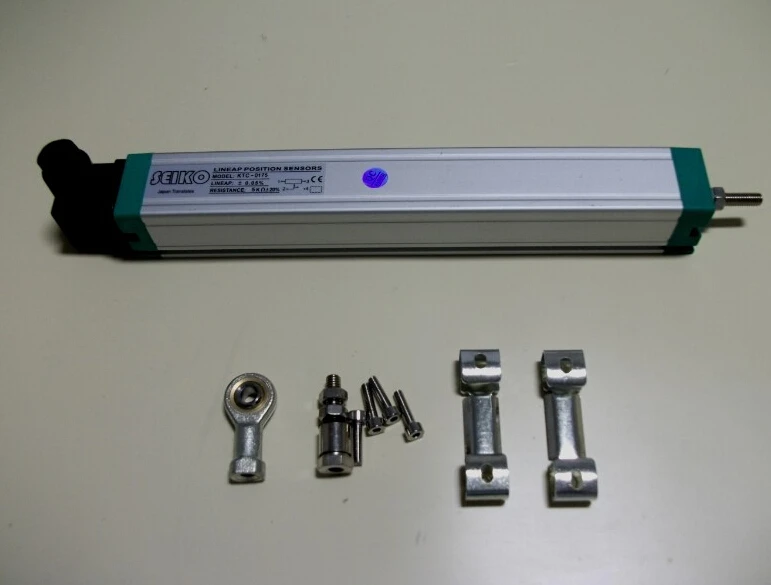
And measuring distance, that's the tricky part. A slide potentiometer would work, but they have limited lifetimes, measured in the hundreds of thousands of strokes. I imagine these will be exceptionally noisy, but they are cheap and can be had for less than $10 for around 100mm travel.
There are slide pots with lifetimes in the millions of cycles, I think I've found chinese resistive linear displacement sensors, I think that means linear slide pot? This is probably what I am going to go with here.
To make everything work all I think I need is a 5v power supply, a nice ADC, and an arduino. I don't know squat about arduino or coding for arduino, but that's next on my huge list of things to search through. Sure could use whatever advice I can get there!
The end goal is pretty simple, log everything as fast as possible to a SD card. When I say log everything, I mean log two ADC values for position and force. After that is done, math will have to be done on the results which can then be plotted in excel or something.
Anyone have any recommendations for good high-res arduino compatible ADCs?
I work with many of these components, and I might be able to get you a good pot for free.
Unfortunately, I won't be able to check my inventory for a few days.
In the meantime, I would be willing to contribute a few bucks to this project.
Writing code for an Arduino is just C. You probably want a timer interrupt to gather the data, store it in an event queue, and then dequeue the data in the main loop and push it out to the SD card. Alternately, you could just push it out over the serial/USB port and log it on the laptop, which will take less CPU power on the arduino.
Is that load cell amplified? If not, I think you're going to need an instrumentation amplifier to read it.
Why do you need more than 10 bits of ADC resolution? As long as your analog gain is appropriate (which is tunable with an external resistor in many instrumentation amplifiers), I would think the internal Arduino ADC is good enough to read that load cell?
All right, another thread to talk about this stuff in.
So hi, I've messed with this a bit too. My last iteration was built off a C channel with stuff I had laying around, plus a 5 port solenoid valve and a pneumatic proportional regulator I got off ebay. Sensors were a velocity transducer I got off ebay plus a pressure transducer to calculate force It let me get results like thus:
(random Koni wet kit strut)
I had it all controlled through a Labjack - a DAQ with decent IO that was programmable in Python. Nowadays I'd use some of the cheaper USB Labview hardware - but that's at least partly because it annoys me to have to code things like this.
To get a force vs velocity plot quickly, you need to be able to do a sine curve like a crank dyno - this will get you every velocity your system will do in one stroke. To do it slowly the way I was, you need a way to vary pressure - this will get you one force per stroke. Notice how that chart above is granular on the vertical axis? That's why. Unless you have a huge air compressor, it might take a while to do the "slowly" way because you'll be using a lot of air; my shop air setup was something like an 80 gallon compressor and I had a reservoir right at the valve because air line quick disconnects restrict flow.
The version I'm working on will use castings (another project of mine) and aluminum extrusion for mechanicals, plus a pneumatic servovalve to let me mess with flow at relatively high frequencies.
I work with many of these components, and I might be able to get you a good pot for free.
Unfortunately, I won't be able to check my inventory for a few days.
In the meantime, I would be willing to contribute a few bucks to this project.
I like to order things from aliexpress, so I'm about to order a bunch of stuff that'll probably be on the slow boat till next year. This stuff's so cheap though, it's probably almost cheaper to ship a new one from china compared to a flat rate box from you! I think it would be nice to order commonly available parts, too, in case anyone wants to copy me in the future.
Thanks for the offer on contributions, but it's not necessary!
Originally Posted by codrus
Writing code for an Arduino is just C. You probably want a timer interrupt to gather the data, store it in an event queue, and then dequeue the data in the main loop and push it out to the SD card. Alternately, you could just push it out over the serial/USB port and log it on the laptop, which will take less CPU power on the arduino.
Is that load cell amplified? If not, I think you're going to need an instrumentation amplifier to read it.
Why do you need more than 10 bits of ADC resolution? As long as your analog gain is appropriate (which is tunable with an external resistor in many instrumentation amplifiers), I would think the internal Arduino ADC is good enough to read that load cell?
--Ian
I need to get a C for dummies book, I don't know squat about coding.
I do like logging straight to a laptop though, if it will be easier to accomplish. It will probably make it a lot easier to keep track of runs with everything writing right to the laptop, too.
My understanding on the load cell is I can get away without amping the load cell with finer resolution, but when is more resolution not bad. Also, I did not know the arduino had built in ADC of any kind lol
I ordered something that might do something handy, I need to learn more to be 100% sure. It's a dual channel 24 bit ADC for arduino, or any serial output I guess. I only need one load cell, but might I be able to use the second channel for the pot? More resolution is always better, right? It would also be awesome if I could find a suitable one of those smaller arduinos in the future, so I can pack everything in a nice neat project box. I'll be using a mega 2560 for now, or a china clone of one. Something I have left over from 3d printer projects.
Originally Posted by 2manyhobyz
^^^^^^^^^^ I would also be willing to contribute funding toward this research.
Deezums, please post Paypal info.
I would, but I don't want you all paying me for all this china junk! Maybe later when I have good results of all sorts of commonly available bilstein stacks and gas pressures
Originally Posted by mekilljoydammit
All right, another thread to talk about this stuff in.
So hi, I've messed with this a bit too. My last iteration was built off a C channel with stuff I had laying around, plus a 5 port solenoid valve and a pneumatic proportional regulator I got off ebay. Sensors were a velocity transducer I got off ebay plus a pressure transducer to calculate force It let me get results like thus:
(random Koni wet kit strut)
I had it all controlled through a Labjack - a DAQ with decent IO that was programmable in Python. Nowadays I'd use some of the cheaper USB Labview hardware - but that's at least partly because it annoys me to have to code things like this.
To get a force vs velocity plot quickly, you need to be able to do a sine curve like a crank dyno - this will get you every velocity your system will do in one stroke. To do it slowly the way I was, you need a way to vary pressure - this will get you one force per stroke. Notice how that chart above is granular on the vertical axis? That's why. Unless you have a huge air compressor, it might take a while to do the "slowly" way because you'll be using a lot of air; my shop air setup was something like an 80 gallon compressor and I had a reservoir right at the valve because air line quick disconnects restrict flow.
The version I'm working on will use castings (another project of mine) and aluminum extrusion for mechanicals, plus a pneumatic servovalve to let me mess with flow at relatively high frequencies.
I was planning on using flow control valves on the exhaust ports to try and hit as many shaft speeds as necessary and as smoothly as possible, it seems this'll probably be a primitive way of doing what you did? Between using the output regulator on my compressor and a simple and cheap pair of bleed valves I figured I'd be able to measure enough smooth data to put together a solid plot. With as much stroke as I'm hoping I'll be able to work with, I was planning on fiddiling the bleed valves while all was in motion too. Donno, guess that'll all be stuff to play with once I get there.
I was considering extrusions for the frame, but that stuff is spendy. I think I'll probably end up welding a frame up pretty much exactly like the blue one I posted above. If I use 3/16 2x3" tube I think I can have it done up for ~$70. I don't think I'll need much more than a bandsaw and mig welder, some center punches and a drill press. Mounting the ram is probably gonna be the most complicated part!
To get me started I ordered all the electronic bits, that way I can poke at stuff and see if I can get reasonable measurements. Seems like a pretty decent starting point.
So after shipping and everything I'm at $85.00. Looks like I might blow right past my "one bilstein shock" budget unless I find some recycled frame. That's cheating, though
I need to get a C for dummies book, I don't know squat about coding.
My understanding on the load cell is I can get away without amping the load cell with finer resolution, but when is more resolution not bad. Also, I did not know the arduino had built in ADC of any kind lol
I ordered something that might do something handy, I need to learn more to be 100% sure. It's a dual channel 24 bit ADC for arduino, or any serial output I guess. I only need one load cell, but might I be able to use the second channel for the pot? More resolution is always better, right? It would also be awesome if I could find a suitable one of those smaller arduinos in the future, so I can pack everything in a nice neat project box. I'll be using a mega 2560 for now, or a china clone of one. Something I have left over from 3d printer projects.
I'm a software guy, not a EE, but I've spent a bit of time playing with Arduinos on car projects lately. I picked up an unamplified pressure sensor a couple weeks ago (intending to use it to build a DIY rotary engine compression tester), which is basically just a load cell and a diaphragm. The max output value of it is measured in tens of millivolts, as a differential voltage between two pins. It *is* possible to fix that in software, but you need a super high resolution ADC so that you can read both pins and compare them to get the differential value. Or you just buy a $6 INA125P, feed the + and - pins to it, give it an appropriate size resistor to set the gain, and now you've got a nicely scaled 0-5v signal that you can easily read with the built-in ADC. Or, at least, that's my understanding -- I haven't actually done it yet.
And yes, the Arduino has a built-in ADC, it's what the analog pins are all hooked up to. There's only one (it's reallocated to whatever analog input pin you're using at the moment), it has 10 bits of resolution, and it's not super fast (maxes out at 10K samples per second, I think), but it's plenty for these sorts of purposes. 10 bits gives you resolution of 0.1%, assuming your input signal is using the whole range.
I like the mega2560, not just because it shares a part number with a turbo that's a good match for a Miata but also because it's got 4x the ram of the normal arduino uno. It's not hard to overflow the 2K of ram on the small ones if you're using a bunch of libraries and String types.
I am actually an EE, so if you need help with the electronics and/or C code let me know.
For your linear potentiometer, just use the internal ADC of the Arduino, it will be fine. The linear pot from AliExpress looks quite nice actually.
For logging I would just spit out the data through UART/USB and store it on the PC. In my opinion it does not make much sense to use a SD card for that, only makes it more complicated.
One thing I do not understand is why you want a manual valve to control the ram, would it not make much more sense to use electronic valves and control them through the Arduino?
Given you have plenty of air you might be able to control velocity of the ram quite well if you PWM the control valves (just like an EBC).
For all intents and purposes, you need to amplify load cells. It's horrible to do anything with them otherwise; the electrical signals will be right around the noise threshold and any reasonable load will be close to the resolution limits of any reasonable ADCs. That load cell you posted outputs 2mv/V at full scale - that means that at a 5v excitation, at 1100lb of force, you'll get 10mV back. The 10 bit Arduino ADCs have a resolution of 4.9mV, or in other words you'll maybe see a difference between 0 and 500 pounds and 500 and a thousand. 24 bit ADC means you likely get 20 bits effective (just an ADC noise thing) which is actually a lot - about 2 pound resolution without amplification - so you can get away with it, but it's still a better idea to use a load cell amplifier.
*quickedit* Actually, it looks like that specific ADC does amplification on-chip and is specifically made for load cells, so that should work fine.
Bleed valves could work - yeah, it basically works out to the same sort of thing I was doing, just you'll be changing the force by increasing pressure on the outlet side not reducing it on the inlet side. I like the idea of long stroke shock dynos, but gas pressure is going to be another variable. I had in mind the testing program stroking everything slowly at first and looking at force vs displacement to be able to correct for gas pressure to be able to cut it out of the cleaned up data. If you're stroking the shock at one force per stroke (for argument's sake I'm going to pretend it's a pressure regulator like I did) you can average the velocity to correct out the gas pressure, but if you're trying to vary velocity during the stroke you need to do something more exact or you'll get garbage data.
I'm doing extrusion because I did my first cut where I welded everything together out of scrap; it worked and all but now I'm trying to do better.
Doing electronic valves are kind of weird - I'm honestly not sure a MAC style valve would work right. Like I said, I ended up having a pneumatic proportional regulator and a shuttle valve, which worked great except the shuttle valve was air piloted so wouldn't switch over at very low pressures. Actually, I think I still have them kicking around in my barn - given I'm going an even better control scheme, I might be talked into kicking them over.
I've done a bit more working on this thing in my free time. Not sure what I was thinking ordering a 32mm bore cylinder, that thing will only be good for 135lb of force at the most. To get to the pressures I'd like to measure the high speed, I think I need an 80mm bore cylinder.
A 32mm bore 150mm stroke ram at 15 cycles a minute and 110psi needs around 1.4SCFM if my math is right. An 80mm bore and same stroke and 10 cycles per minute would require more than 8scfm at 110psi, not something I think I can do. But, that would generate over 900 pounds of force. I can run a 32mm bore cylinder pretty easy, but 1.5scfm at 110 psi is probably about all I've got.
I think I might go back to a lever to provide the force, if I mount the linear potentiometer coaxially on the shock body itself I should be able to make it happen pretty easy. Or, I can swing the $50 for a larger ram of half the stroke (75mm) and hope my compressor keeps up. Can't decide, all I know for sure is my switch valve should flow enough volume to move an 80mm ram at 110 psi still, without too much pressure drop.
If you're doing compressed air, the high load cycles will use a lot of air. Trick is, you'll only be using 8scfm for a second or so, so if you put a reservoir right by the inlet to the valve to take quick disconnect losses out of the factory, it can keep up as long as you're not cycling it back and forth *too* fast.
Do keep in mind that most of the interesting stuff is slower speed anyway.
Hm, yeah. The pneumatic dyno can do different things though, but with the cost of VFDs nowadays I bet I can score a couple horsepower 3 phase motor off Craigslist for pretty cheap. I had kind of forgotten that a lot of the reasoning behind the pneumatic dyno back in the day was "hey, a pile of parts I can use".


 0
0