

3d printed intake for N/A NA miatas


Thread Starter

Joined: Jul 2012
Posts: 792
Total Cats: 143
From: durham NC
Hi Everyone,
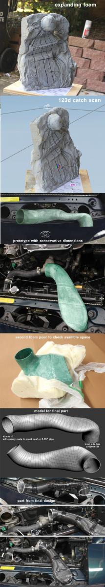
There are a few people running VVT motors in NA miatas here so I thought I would post this even though it isn't turbo related. I have been working on a 3d printed intake duct that draws in ambient air from the front bumper (similar to the joefis intake).
Basic specs for the intake:
*Inlet side has an ID of 65mm, the exit of the intake has an ID of 67mm.
*The total intake tract length from the tip of the duct to the throttle body ends up being about 26" with the ability to shorten the intake by about 2 inches on the inlet side. This is slightly longer than I had hoped, I may end up making a new design that wraps at a different angle for a shorter length.
*The area of any given cross section from the intake should only deviate by a few percent.
*This cost me $35 to print in ABS plastic using a local printer found on MakeXYZ. I can direct people to him if they are interested.
I am uploading the 3d model for people to print their own versions or make alterations to. If you do print one, I would suggest you user either ABS or nylon. PLA will likely fail at these temps. Also, I am considering this a prototype so far. I have been talking with the printer about doing a very thin walled version in PLA, then fiberglass over top, and then solvent melting the PLA away from the model. The ABS version appears to be fine in the short term. The plastic doesn't melt or deform from the heat, but I think getting heat cycled it will eventually become brittle and break.
Dunning Kruger Affect is going to A/B dyno test this over the winter. The part is designed for auto-x where you will be idling in grid with no airflow before launching. My hope is that directly drawing in ambient air will help with IATs at the start of a run.
I am linking to a large image showing the design and construction process. Note that this is printed in several sections and I had the printer focus all finishing efforts on the interior surface. The exterior has not been heavily sanded or vapor treated. Also, that isn't tape at the joints, it's solvent bonded ABS wrap.

Last edited by asmasm; Nov 25, 2013 at 04:37 PM.
Reply
 11
11

11
Thread Starter
Joined: Jul 2012
Posts: 792
Total Cats: 143
From: durham NC
Link to an STL file for the completed intake:
NA miata intake duct by AlecMoody - Thingiverse
If anyone wants the cut up version let me know.
NA miata intake duct by AlecMoody - Thingiverse
If anyone wants the cut up version let me know.
Reply
0
0


Elite Member
Joined: Apr 2010
Posts: 2,826
Total Cats: 66
From: Newcastle, Australia
Can I just give this file to a mate and have it print the whole thing?
I don't have the right software to look just yet, is there a full version that runs all the way to the throttle body?
Dann
I don't have the right software to look just yet, is there a full version that runs all the way to the throttle body?
Dann
Reply
0
0
Thread Starter
Joined: Jul 2012
Posts: 792
Total Cats: 143
From: durham NC
A full plastic version to the throttle body would break under the engine's movement. All this needs is a silicone elbow, some couplers, and about 8" of 2.75 pipe. I might make a 3d printed crossover that reduces from 2.75 to 2.5 over 6" to provide a clean way to downsize for my stock throttle body.
If the person you know has a printer that can accommodate an object this size, it can be printed as one piece. The printer I am using is in the process of building a larger cylindrical printer so we can make them in one print.
If the person you know has a printer that can accommodate an object this size, it can be printed as one piece. The printer I am using is in the process of building a larger cylindrical printer so we can make them in one print.
Last edited by asmasm; Nov 23, 2013 at 05:53 PM.
Reply
0
0

Senior Member
Joined: Sep 2013
Posts: 923
Total Cats: 67
I can't wait to A/B test this!
I know Emilio puts the air intake on the intake side with a U piece, and most people just run a crossover tube to make it a hot air intake with a heatshield. This should significantly lower intake temps because it does get more than mildly warm on the exhaust side even with an exhaust blanket.
I know Emilio puts the air intake on the intake side with a U piece, and most people just run a crossover tube to make it a hot air intake with a heatshield. This should significantly lower intake temps because it does get more than mildly warm on the exhaust side even with an exhaust blanket.
Reply
0
0
Thread Starter
Joined: Jul 2012
Posts: 792
Total Cats: 143
From: durham NC
I can take another look but it should be roughly equal through the squished section. It's hard to know how to slice out a cross section when you don't know the exact direction the air is traveling. The exit half of the intake (after the squish) slowly tapers up in size by a few mm.
Reply
0
0

Cool stuff. ABS is the right choice here. Did your printer have enough resolution to make a water/air tight model? The one we had at school wasnt quite air tight so it required a sealant. I believe I bought some model aircraft spray on ABS sealant from amazon for like $20 a can that worked.
How thick is the ABS? If its thinner than 1/4" you might want to consider laying FG over it, even chop mat to make sure it doesnt break with intake backfires.
How thick is the ABS? If its thinner than 1/4" you might want to consider laying FG over it, even chop mat to make sure it doesnt break with intake backfires.
Reply
0
0
Thread Starter
Joined: Jul 2012
Posts: 792
Total Cats: 143
From: durham NC
The wall thickness is 3mm. If I can find a way to create a good bond between abs and fiberglass I think that method would work well. Without a good bond I think an intake backfire would just shatter the abs material and suck it into the engine.
Leafy, you have the joefis intake- right? When I have a final version done, it would be interesting to A/B them. The joefis intake duct shape has a few areas that look questionable to me. However, I'm not an engineer and I wouldn't claim to know what kind of work went into his design.
Leafy, you have the joefis intake- right? When I have a final version done, it would be interesting to A/B them. The joefis intake duct shape has a few areas that look questionable to me. However, I'm not an engineer and I wouldn't claim to know what kind of work went into his design.
Reply
0
0
Thread Starter
Joined: Jul 2012
Posts: 792
Total Cats: 143
From: durham NC
I will look into the west system and experiment with different wall thicknesses. The printer I am working with will be able to do this part in a single print some time in January, which I think is preferable for getting a smooth finish inside and out.
I am also going to experiment with different filter options and see what fits. I would prefer something relatively short and squat to reduce the chance of sucking in water.
I am also going to experiment with different filter options and see what fits. I would prefer something relatively short and squat to reduce the chance of sucking in water.
Last edited by asmasm; Nov 25, 2013 at 07:20 PM.
Reply
0
0
We've blown apart intake ducting post filter on the CSP car. Granted the backfire was cranking at WOT to flood clear because the cam trigger wheel had slipped on the back of the cam.
Reply
0
0
Thread Starter
Joined: Jul 2012
Posts: 792
Total Cats: 143
From: durham NC
If anyone is messing with the 3d file- I am making an update to help even out the area. This is a graph of the square mm at 14 cross sections for the newest design:
http://gyazo.com/114ae1d3e118ad50370ec98c61f510b2.png
I might do another pass on it when I have more time later.
http://gyazo.com/114ae1d3e118ad50370ec98c61f510b2.png
I might do another pass on it when I have more time later.
Reply
0
0
Thread Starter
Joined: Jul 2012
Posts: 792
Total Cats: 143
From: durham NC
I made a more illustrative graphic. I added lines for the ID of 2.75 and 2.5 aluminum tube (assuming a 2mm wall thickness):
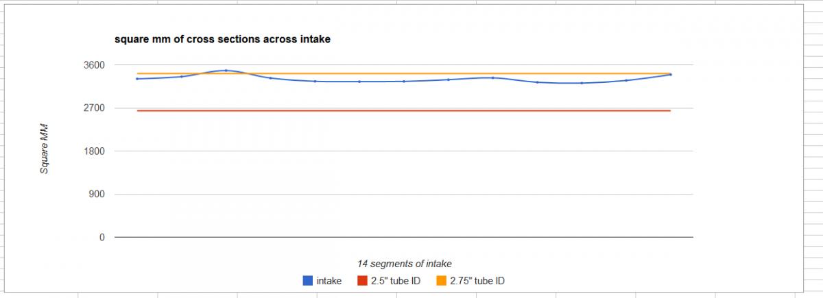
I have a 2.5" tube in front of me and it is actually a little bit undersized, I don't know if that is standard or specific to my tube.
I have a 2.5" tube in front of me and it is actually a little bit undersized, I don't know if that is standard or specific to my tube.
Reply
0
0


