

3d printed intake for N/A NA miatas


Thread Starter
Joined: Jul 2012
Posts: 792
Total Cats: 143
From: durham NC
Reply
 0
0

0

Reply
0
0
Thread Starter
Joined: Jul 2012
Posts: 792
Total Cats: 143
From: durham NC
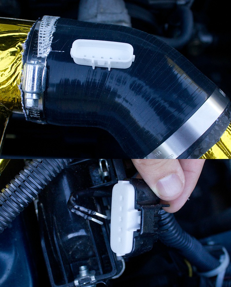
It's for a 1.8. I will share the file when it is finalized but I still need to add some way to get the pins to hook into the connector. I can't do it exactly the same way as the OEM plug since those details are too small to print reliably.
Last edited by asmasm; Sep 6, 2014 at 12:10 PM.
Reply
0
0

Some day? I have a vacuum pump on its way to me and I will pick up the fiberglass supplies I need to make molds. I also need to get a new version 3d printed to be the plug. This part is fairly technical to lay up since it is a split mold that is too narrow to fit your hand into.
One nice thing about the carbon versions is the 1mm wall thickness will allow me to fit a 2.5" flange filter without having to change the inner diameter. I just ordered a filter with perfect dimensions that is only $30 compared to the $55 K&N I have been using.
Also, is there anyone in durham with a 1.6l car and a stock engine I could measure off of? I think I need to make a crossover for 1.6 cars that makes an arc to clear their coolant hoses and thermostat neck.
When the layup cures you will end up with a tube that you can build further with proper external layup's with a tubular vacuum bag inside (so you do not crush or distort the hole thing) and another bag one over the outside with peel ply and absorbent mat.
Good luck
Reply
0
0
Thread Starter
Joined: Jul 2012
Posts: 792
Total Cats: 143
From: durham NC
Iv had good luck making a two piece female mold that are bolted together, i then put strips of byest cut fiverglass or carbon with the ressin on it along the walls of the mold and then inset an inner tube section inside the center and presurize it.
When the layup cures you will end up with a tube that you can build further with proper external layup's with a tubular vacuum bag inside (so you do not crush or distort the hole thing) and another bag one over the outside with peel ply and absorbent mat.
Good luck
When the layup cures you will end up with a tube that you can build further with proper external layup's with a tubular vacuum bag inside (so you do not crush or distort the hole thing) and another bag one over the outside with peel ply and absorbent mat.
Good luck
My goal is to be able to do them in one shot using biaxial sleeves but if that doesn't work laying them up on the split mold is my backup plan. The inner diameter is too small to fit a hand inside but i can do one side oversized and use a flap that overlaps them.
Reply
0
0
Is the most cost efficient way
Reply
0
0

Junior Member
Joined: Dec 2008
Posts: 315
Total Cats: 9
From: Ft. Lauderdale, FL
Some details of the car:
'90
VVT Motor (Unopened junk yard motor)
Flat Top Intake manifold
DIYPNP
VVTuner
'99 IAT sensor
Racing Beat Header
Custom 2.5" madrel exhaust with an 18" Hushpower muffler
Custom intake with open filter
Car makes 143HP with its current tune and I am looking for more. I would be very happy to test it for you and send you any information you need.
My current dyno graph:
racing beat header.pdf
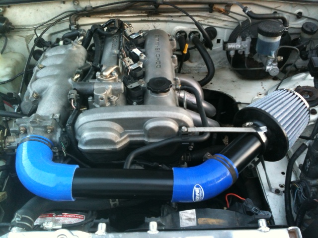
My current intake set-up (Picture is prior to Flat Top install):
Reply
0
0
Thread Starter
Joined: Jul 2012
Posts: 792
Total Cats: 143
From: durham NC
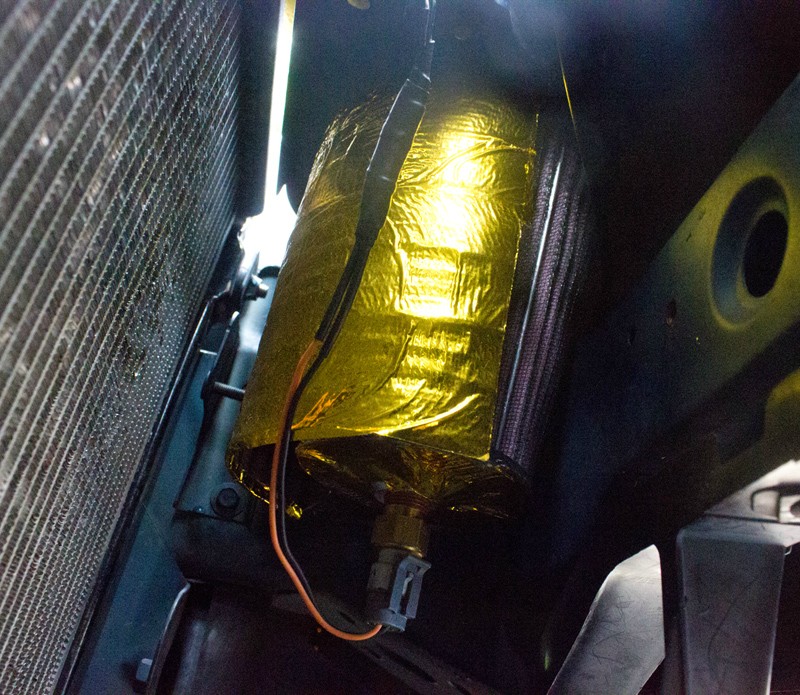
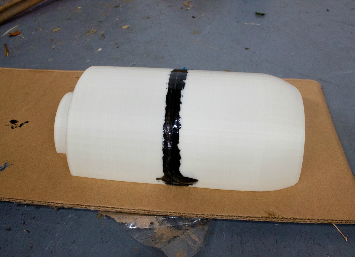
I finally got a hacked together heat shield installed. It is several carbon fiber layups bonded together with foil on the back:
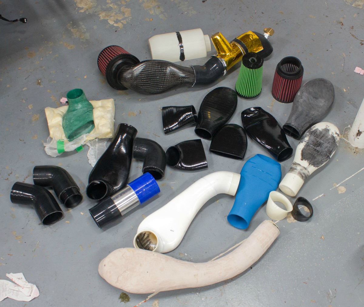
Also, I have been playing around with tubing wall thickness and elbow diameters. This stuff is all 2.5" except where it hooks up to the duct (which currently has about 3.5mm wall thickness):
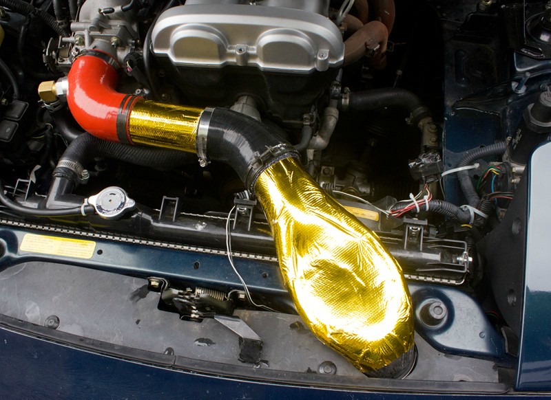
That crossover has an inner diameter of 63.5mm but the wall thickness is only .75mm so it fits well in a 2.5" elbow. If you measure silicone elbows and aluminum tubes there is significant stepping up and down in size at each joint. This might not have a huge effect on performance but making carbon tubes is really easy and inexpensive and any added cost is offset by cheaper elbows and filters. Some numbers:
Stock TB is 53mm
Skunk2 TB is 64mm
2.5" elbows have an ID of 64mm
2.75" elbows have an ID of 70mm
2.75" aluminum tubing has in an ID of 65mm but because the walls are slightly more than 2mm thick the elbow needs to be 5mm larger than that to accommodate it. The final duct will have an ID of 62.5mm but only 1mm of wall thickness. As a result it will use a 2.5" filter and 2.5" elbows. The complete filter to TB intake will only deviate by ~2mm. On the setup Curly tested there was a lot more deviation than that (62.5mm to 70mm).
Also, I have been playing around with tubing wall thickness and elbow diameters. This stuff is all 2.5" except where it hooks up to the duct (which currently has about 3.5mm wall thickness):
That crossover has an inner diameter of 63.5mm but the wall thickness is only .75mm so it fits well in a 2.5" elbow. If you measure silicone elbows and aluminum tubes there is significant stepping up and down in size at each joint. This might not have a huge effect on performance but making carbon tubes is really easy and inexpensive and any added cost is offset by cheaper elbows and filters. Some numbers:
Stock TB is 53mm
Skunk2 TB is 64mm
2.5" elbows have an ID of 64mm
2.75" elbows have an ID of 70mm
2.75" aluminum tubing has in an ID of 65mm but because the walls are slightly more than 2mm thick the elbow needs to be 5mm larger than that to accommodate it. The final duct will have an ID of 62.5mm but only 1mm of wall thickness. As a result it will use a 2.5" filter and 2.5" elbows. The complete filter to TB intake will only deviate by ~2mm. On the setup Curly tested there was a lot more deviation than that (62.5mm to 70mm).
Last edited by asmasm; Sep 9, 2014 at 06:37 PM.
Reply
1
1

Thread Starter
Joined: Jul 2012
Posts: 792
Total Cats: 143
From: durham NC
I logged the second half of an hour of tuning veal. During the log I am merging onto a 70mph highway, cruising for a mile, and taking the next exit to repeat the process. The IATs are reading ~2.5 over ambient with the sensor in the air filter and the heat shield in place. FWIW the log starts with the car up to temp and the ambient temp climbed about 5 degrees as the sun came out.
This is comparable to what I recorded at cruise with the dual wall crossover so I am inclined to think there is very little heat transfer into the large amount of air flowing through the intake.
Also, I autocrossed this intake through rain and puddles last weekend. No water ingestion issues and my IAT sensor didn't seem to care about getting wet.
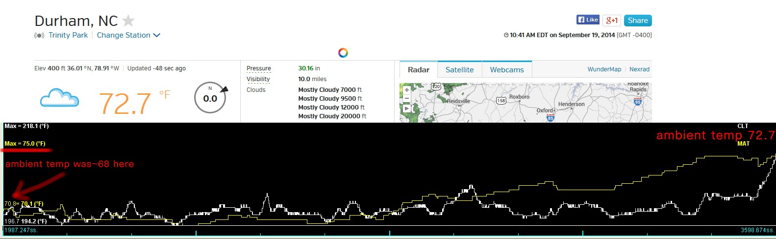
Reply
0
0
Nice progress. Have you played with the gap between the heat shield and filter at all? If its too close your going to load up the open side of the filter with dirt much quicker than the rear. This will increase the pressure drop through the filter faster and shorten the filter life between cleanings.
But I guess you could also just rotate it 180 very easily.
But I guess you could also just rotate it 180 very easily.
Reply
0
0
Thread Starter
Joined: Jul 2012
Posts: 792
Total Cats: 143
From: durham NC
I hadn't thought about dirt accumulation. I did design the heat shield to be as large as is practical so it wouldn't have an impact on flow into the intake. There will be about 1.5" of air space at the base and about 2" at the filter tip.
I have all my 3d prints now and I am taking them with me on vacation so I can get them sanded and polished to a mirror surface.
I have all my 3d prints now and I am taking them with me on vacation so I can get them sanded and polished to a mirror surface.
Last edited by asmasm; Sep 19, 2014 at 12:00 PM.
Reply
0
0

Alec,
Which file is the latest and greatest for the intake?
Version 1.0 dated 7/18/2014 from your Cold Air Intake website?
Or the Version 7 STL file from over on Thingiverse Project 189320?
About to send one off to a local printer... and not sure which is the most current file.
Thanks!
Which file is the latest and greatest for the intake?
Version 1.0 dated 7/18/2014 from your Cold Air Intake website?
Or the Version 7 STL file from over on Thingiverse Project 189320?
About to send one off to a local printer... and not sure which is the most current file.
Thanks!
Reply
0
0

We just had our first track day with the '93 running your intake. He had a hoot, shaving 2 seconds of his best time, with the only change being MS and the intake on his 1.6.
Lots of comments on the funny looking intake, tried to point them this way, but we had 4 turbo miatas, a rotrex, and V8 miata. So they wouldn't exactly work.
Lots of comments on the funny looking intake, tried to point them this way, but we had 4 turbo miatas, a rotrex, and V8 miata. So they wouldn't exactly work.
Reply
0
0
The v8 guys would love a similar design through, so it would be just like the stock vette intake, except either split between the two holes or through the big trapezoid in the middle if they wanted to run without a hood latch.
Reply
0
0
Thread Starter
Joined: Jul 2012
Posts: 792
Total Cats: 143
From: durham NC
There is an aftermarket corvette intake that looks a lot like a bigger version of mine:
Halltech Super Beeline� 102 Carbon Fiber Stage 1, Halltech, Intake, Carbon Fiber intake, CF102, CF112,
I could do something that went down the center or a giant piece that forked off to both of stock holes. It would be a lot more expensive but people who can afford LS swaps might be willing to pay for it.
I wish I could pick halltech's brain and find out exactly how they do their layups. The weave looks continuous which would suggest they are using a bixial sleeve and a wet layup. Getting a totally pinhole free finish like theirs with a biaxial sleeve isn't easy. My parts will likely have small cosmetic flaws but they will be plenty strong waay cheaper. Alternatively, people can pay $1000 per kit and I can get aluminum tooling made and use pre-preg. I doubt the miata crowd is going to be interested in $1000 intakes.
Reply
0
0


