

3d printed intake for N/A NA miatas


Thread Starter

Joined: Jul 2012
Posts: 792
Total Cats: 143
From: durham NC
Yeah. The models need to be water tight no open edges or self intersections. I usually make sure I get rid of all ngons and only have quads and triangles. 3dsmax has a modifer called STL check that will tell you if the mesh passes - then just Export>STL. Also, I use shapeways to double check scale and units are set correctly.
Reply
 0
0

0


Thread Starter
Joined: Jul 2012
Posts: 792
Total Cats: 143
From: durham NC
Curly will probably jump in with more details but he sent me info on the dyno results for stormin'normans car:
Stormin's stash of memories with Lexi - Page 70 - ClubRoadster.net
This is a dyno graph of a coldside U bend intake VS the setup I sent to curly. Mine is the green line:
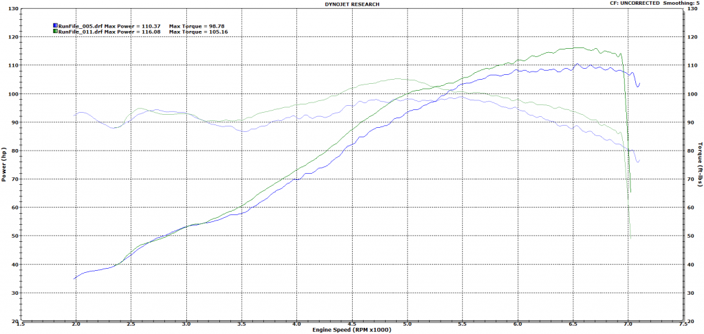
Very encouraging results and I will try and get carbon versions and heat shields going soon.
Stormin's stash of memories with Lexi - Page 70 - ClubRoadster.net
This is a dyno graph of a coldside U bend intake VS the setup I sent to curly. Mine is the green line:
Very encouraging results and I will try and get carbon versions and heat shields going soon.
Reply
2
2

So over the course of a 4th gear pull the intake air temps would drop anywhere from 8-15 degrees. On one of the later runs the temp started at 90 (ambient was low/mid 70s) and dropped to 75 by the end of the pull. It consistently did this over and over. I am inclined to believe that this intake is a worthwhile benefit on an NA miata and I'd love to trial it further on orego moms upcoming VVT swapped NA.
Reply
0
0
Thread Starter
Joined: Jul 2012
Posts: 792
Total Cats: 143
From: durham NC
Were those IATs for both intakes?
Edit: Really what I am wondering is if it is possible to figure out how much gain is from cooler air vs the dynamics and flow of the intake path. I know from my testing on the highway that the IATs are very close to ambient when driving. If the intake itself actually does as well or better than the other design when IATs are taken out of the equation that is a huge win.
Edit: Really what I am wondering is if it is possible to figure out how much gain is from cooler air vs the dynamics and flow of the intake path. I know from my testing on the highway that the IATs are very close to ambient when driving. If the intake itself actually does as well or better than the other design when IATs are taken out of the equation that is a huge win.
Reply
0
0
That was for your intake, the coldside intake would heatsoak and stay roughly the same temperature during the pulls whereas your design consistently cooled the intake temps every time.
Reply
0
0

Once you do a pull it really starts sucking in cooler air, and yours was cooling down 5-15 degrees during a pull. I did a datalog for every pull, I'll post them soon.
Reply
0
0

Thread Starter
Joined: Jul 2012
Posts: 792
Total Cats: 143
From: durham NC
The logs would be great. I want to pick a handful of points along the dyno curves for each intake, look at the IAT, and then try a rough correction for how each of them compare if the IAT were the same. That should give me a good sense for how much power is temp related and how much is intake geometry. From the description it sounds like its about 50% of each going on. That air temp difference is going to be something like a 3% density change. I am very confident that I can functionally eliminating heat transfer from the engine bay or radiator into the intake air (at least until it gets to the very hot intake manifold).
Reply
0
0
Thread Starter
Joined: Jul 2012
Posts: 792
Total Cats: 143
From: durham NC
I did a data log of the IAT with the sensor in the filter. It still heat soaks a little. On an 80 degree day I am seeing 95 degrees after getting everything totally hot and then letting it sit for 15 minutes before restarting the engine. That is way better than before when I had 140f MAT in the same circumstances.
Also, these GM IAT sensors seem to react to big air temp changes on a curve. Like on hot restart It will quickly drop 5-7 degrees but then progressively more slowly get back to the actual air temp. It seems to take at least 5 minutes to get back to being accurate but the last few degrees doesn't make a impact on AFRs.
Also, these GM IAT sensors seem to react to big air temp changes on a curve. Like on hot restart It will quickly drop 5-7 degrees but then progressively more slowly get back to the actual air temp. It seems to take at least 5 minutes to get back to being accurate but the last few degrees doesn't make a impact on AFRs.
Last edited by asmasm; Aug 17, 2014 at 06:49 PM.
Reply
0
0

Thread Starter
Joined: Jul 2012
Posts: 792
Total Cats: 143
From: durham NC
Some day? I have a vacuum pump on its way to me and I will pick up the fiberglass supplies I need to make molds. I also need to get a new version 3d printed to be the plug. This part is fairly technical to lay up since it is a split mold that is too narrow to fit your hand into.
One nice thing about the carbon versions is the 1mm wall thickness will allow me to fit a 2.5" flange filter without having to change the inner diameter. I just ordered a filter with perfect dimensions that is only $30 compared to the $55 K&N I have been using.
Also, is there anyone in durham with a 1.6l car and a stock engine I could measure off of? I think I need to make a crossover for 1.6 cars that makes an arc to clear their coolant hoses and thermostat neck.
Reply
0
0


ʎpunq qoq
Joined: Jan 2014
Posts: 604
Total Cats: 202
From: Western Australia
I am just printing your intake now just for fun out of PLA. I currently have a 1.6 in my car but am installing a 1.8 in the upcoming months. If you want I'll sit it in the engine bay, take some photos and measure it up for you. I've ordered some ABS so I can print it for use later.
Reply
0
0
Thread Starter
Joined: Jul 2012
Posts: 792
Total Cats: 143
From: durham NC
Yeah basically. I would recommend you look on MakeXYZ and the filter the results by material type (ABS plastic). You will probably need to get it printed in 2-3 pieces. ABS is prone to warping during print and the printers that do the best results are closed off and heated. I have a version in the included files for printing as two parts. You can glue the parts together with abs cement from the plumbing isle at home depot. The joints made with it appear to be stronger than the rest of the part so no issues there. I have also used it to make repairs.
Total cost to get it printed ought to be in the $100-$200 range. Also, make sure they do an acetone vapor bath on the part/parts as it makes them much stronger.
Alternatively, I have a few prototypes kicking around that are only very slightly different than the one I sent to curly. PM me if you want one of them.
Reply
0
0

Adding notches in the part on the cut plane makes gluing together multiple pieces much easier. Especially on circular parts where you can clock the part at the wrong angles when gluing causing misalignment.
3dhubs is another alternative for a local 3D printing source.
3dhubs is another alternative for a local 3D printing source.
Reply
0
0


