When you click on links to various merchants on this site and make a purchase, this can result in this site earning a commission. Affiliate programs and affiliations include, but are not limited to, the eBay Partner Network.
I know that this is a fairly common subject of discussion, but I've not been able to find a simple statement on how to correctly wire a 4 wire 1.8 tps pigtail into a 1.6 wiring harness.
I have the pinout for a 1.8 TPS listed as:
Lt Green / Red = 5vref
Red/Blue = TPS Signal
Red = WOT Switch
Blk/ Blue = GND
Per Brain. And was told by Reverant that I should be able to ignore the 4th wire, in this case the WOT, and just pair up the other 3.
Can someone clue me in to the pinout of a 1.6 TPS plug so I can match the wiring? Or give me a rundown on which color wire should go to which? Or just let me know if I'm somehow missing something and this will not work how I intend it to?
I feel the need to chime in here, for my setup this was incorrect. It may be my MS harness was wired slightly backwards, but in any event I had to reverse the 5vRef and TPS signal (Green with white stripe and I think black/green) wires to get a good reading. What was weird was it did "Work" but would bounce all over the place and my calibration values were like 720-820 when it was wrong, but when I reversed the wires and made it correct these values were 100-800ish (Notice it's a much wider range and thus is less susceptible to noise).
Most important thing is your values in calibration look are about 100-7/800. Otherwise reverse it. As always solid red (tps sensor side) is unused.
This sounds exactly like what I'm dealing with after wiring mine up. I'll try reversing those wires to see what happens. Unfortunately the tps pigtail I am used is from a 94-95 protege (fits the same) and the wire colors are different which means there's a little room for translation error.
I did find this which I think could be helpful for people going forward. (I've not tested it to see if it works yet though, hopefully I'm not propagating bullshit)
I feel the need to chime in here, for my setup this was incorrect. It may be my MS harness was wired slightly backwards, but in any event I had to reverse the 5vRef and TPS signal (Green with white stripe and I think black/green) wires to get a good reading. What was weird was it did "Work" but would bounce all over the place and my calibration values were like 720-820 when it was wrong, but when I reversed the wires and made it correct these values were 100-800ish (Notice it's a much wider range and thus is less susceptible to noise).
Most important thing is your values in calibration look are about 100-7/800. Otherwise reverse it. As always solid red (tps sensor side) is unused.
Thank you so much for posting this as I just finished a 1.8 swap myself and couldn't figure out why my values were stuck between 830 and 999 and moved a lot, I will try this out as soon as I get a chance.
Thank you so much for posting this as I just finished a 1.8 swap myself and couldn't figure out why my values were stuck between 830 and 999 and moved a lot, I will try this out as soon as I get a chance.
Update, tried swapping those two wires and it didn't work. gave me no change or range on the tps reading in MS
I'm still having issues with this myself, after trying with that picture I had found. Its definitely not correct. I'll try with the suggestion that Braineack made today.
Unfortunately I'm using a TPS plug Snipped from a protege and the wire colors are different so there's a small amount of translation to be done.
from a protege and the wire colors are different so there's a small amount of translation to be done.
Follow the Plug order layout on those diagrams and not the colors. I think My TPS must be bad or something because the wiring is setup correctly and the TPS is still all funky, if I even put my fingers on it on the outside or whatever it will adjust its reading.
Seem to have gotten this figured out but my tps gauge still wanders a good 5-10% when left alone. I'm guessing that's probably due to signal noise and I'll probably wrap my signal wire in tin foil or something to try to help it. (At least the solder joint portion).
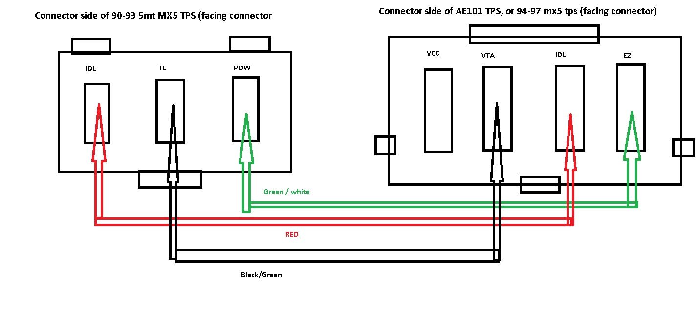
For future generations sharing my struggle, using the pictures above and looking at the 1.8 tps plug with the press release facing upwards.
From left to right:
Pin 1 to Green and White 1.6 wire.
Pin 2 to Red 1.6 wire.
Pin 3 gets left out
Pin 4 to Black and Green 1.6 wire.
Seem to have gotten this figured out but my tps gauge still wanders a good 5-10% when left alone. I'm guessing that's probably due to signal noise and I'll probably wrap my signal wire in tin foil or something to try to help it. (At least the solder joint portion).
For future generations sharing my struggle, using the pictures above and looking at the 1.8 tps plug with the press release facing upwards.
From left to right:
Pin 1 to Green and White 1.6 wire.
Pin 2 to Red 1.6 wire.
Pin 3 gets left out
Pin 4 to Black and Green 1.6 wire.
Your relaying the exact diagram Brain just gave, mine is wired that way but it still is full of issues
Seem to have gotten this figured out but my tps gauge still wanders a good 5-10% when left alone. I'm guessing that's probably due to signal noise and I'll probably wrap my signal wire in tin foil or something to try to help it. (At least the solder joint portion).
For future generations sharing my struggle, using the pictures above and looking at the 1.8 tps plug with the press release facing upwards.
From left to right:
Pin 1 to Green and White 1.6 wire.
Pin 2 to Red 1.6 wire.
Pin 3 gets left out
Pin 4 to Black and Green 1.6 wire.
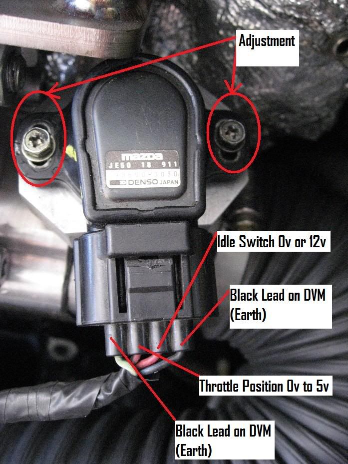
Just as so I can get this pictured exactly correct, you're looking at the sensor like this
(Sorry if formatting is off, did this on the iPhone)
This is a different than how I have mine wired and what I had previously posted above, I'll have to check again but I believe I have pins 1 and 2 backwards from your new image. Mine seems to be reading correctly but the reading wanders after almost every drive by about 10% in one direction or another. I had always just blamed signal noise for this but I may flip some wires around and try it this way. Thanks for uploading this.
I made a much better diagram that's in my 1.6L MS3X and DIYPNP install docs:
OE = 90-93
the above is really confusing. "black lead on DVM" ???? for both the 5v and ground? Nice diagram, *******.
I feel like a bit of an ******* for not coming back and updating this, cus everything else I was reading didn't seem to make sense and other people seemed to be doing it differently, but THIS diagram Brain posted is exactly what I ended up figuring out. I have a question though, what happens if you wire it this way on a stock 1.6 ECU, you lose WOT but if your not running A/C or P/S does that really matter? Asking in case I ever 1.8 swap a car without doing a megasquirt first.
 09-03-2015, 04:20 PM


 0
0