Half Finished ECU -_-
 12-24-2013, 01:50 AM
#1
Newb
Thread Starter

Join Date: Sep 2013
Posts: 32
Total Cats: -2
 So I'v been trying to build up a v3 board with an MS1 processor on it. Only problem is, its been worked on by three different people in the last few years. I'm not even sure what instructions they were running off of. I assume they were planning to run MS-Extra firmware so we could have ignition advance on the MS1. But the board does not look like it was built for that. The ECU is intended to be built for a 94 turbo miata. So I have some questions:
1. I remember reading somewhere that when doing the general assembly of the board (not the mods), it is ok to put all the components on the board. So when the instructions tell you to leave certain components out, you could put those components in and it will not effect the board's operation. Is this true?
2. I have a completed MegaStim that someone completed. Once the general assembly of the board is completed (again, no mods yet), I was planning to test the main board to see if it will respond to the MegaStim's input. Is it possible to test the board using the MegaStim when no mods are on the board?
I've been putting a lot of time into getting to understand this board and I'd really appreciate some advice to get me moving in the right direction. Thanks for your help in advance!

Reply
 0
0

0
12-24-2013, 06:47 AM
#2
Senior Member

Join Date: Nov 2007
Location: Belgium
Posts: 999
Total Cats: 73
1. not always. some people (like myself) populate the non-used parts with custom circuits
2. yes
My advice, ditch the MS1 processor and get an MS2 or MS3 processor. Then follow my guide at Frank's Westfield MX5 |
2. yes
My advice, ditch the MS1 processor and get an MS2 or MS3 processor. Then follow my guide at Frank's Westfield MX5 |
Reply
0
0
12-24-2013, 11:08 AM
#5
Newb
Thread Starter
Join Date: Sep 2013
Posts: 32
Total Cats: -2
It's also worth adding that it is not a plug and play system. I see your instructions are for plug and play. Would it be possible/ make sense to get the 40 pin socket that fits with the miata and make the system pnp?
Last edited by DKdekes; 12-24-2013 at 11:30 AM.
Reply
0
0
12-24-2013, 11:17 AM
#6
Newb
Thread Starter
Join Date: Sep 2013
Posts: 32
Total Cats: -2
Alright I found MS2 by itself at diyautotune:
CPU - MegaSquirt-II Daughterboard DIYAutoTune.com
But it costs over 100. If I could get it to run on MS-Extra with the MS1 processor that would be great. I'm not concerned with optimal performance, I just want the car done. So long as MS1 won't cause my car to stall or detonate I will be happy with it.
Reply
0
0
12-25-2013, 01:50 AM
#7
Newb
Thread Starter
Join Date: Sep 2013
Posts: 32
Total Cats: -2
Santa bump. Will I still be able to safely run the car with an MS1? If not I can buy the MS2 and build using the westfield instructions.
Westfield you said that the general board layout isn't always the same. When would it differ? Only if the person writing the instructions wants to make room for his own custom circuits?
Westfield you said that the general board layout isn't always the same. When would it differ? Only if the person writing the instructions wants to make room for his own custom circuits?
Reply
0
0
 01-10-2014, 01:18 AM
#10
Junior Member

Join Date: Apr 2013
Location: Va
Posts: 87
Total Cats: -4
Well to start off, you have at least listed that the unit is an MS1 processor on a V3 board - you have a decent enough starting platform for things to be fairly easy for you but first you need to answer a couple of questions....
Year of vehicle - 94... Good
Turbo or Na? - Intended turbo....Good
Do you need electronic boost control or intend on using only the wastegate...?
Original 94 engine or a later model engine with VICS or VVT.....?
Low impedance or high impedance injectors....?
Do you want to run batch or sequential injection...?
Can you solder or read an electrical schematic...?
Answer these questions at the very least and provide pictures of the board (both sides clearly showing where any wires go). Many V3 boards or being used on miata's currently and I'm sure we could walk you through it, but be forewarned it is easier to understand how the entire system works and how to troubleshoot it if you take the time to learn how each little component adds to the big picture.
Oh, and MS1 will get the job done but MS2 is much more powerful - plus if you utilize the factory ecu connector you aren't limited to only 4 additional output pins on the DB37 (x11-x14). I'm really liking the EGO resolution on my MS2
Reply
1
1


 01-17-2014, 08:55 AM
#14
Elite Member
iTrader: (1)

Join Date: Jun 2006
Location: Warrington/Birmingham
Posts: 2,642
Total Cats: 42
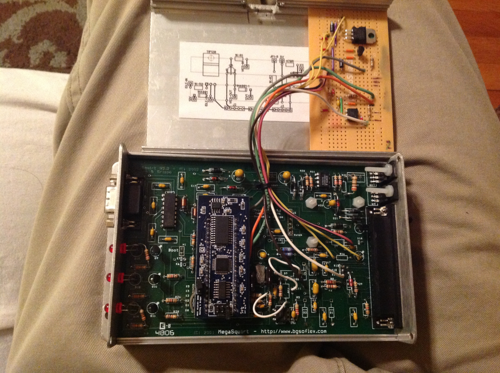
Looks like it does a bunch of stuff.
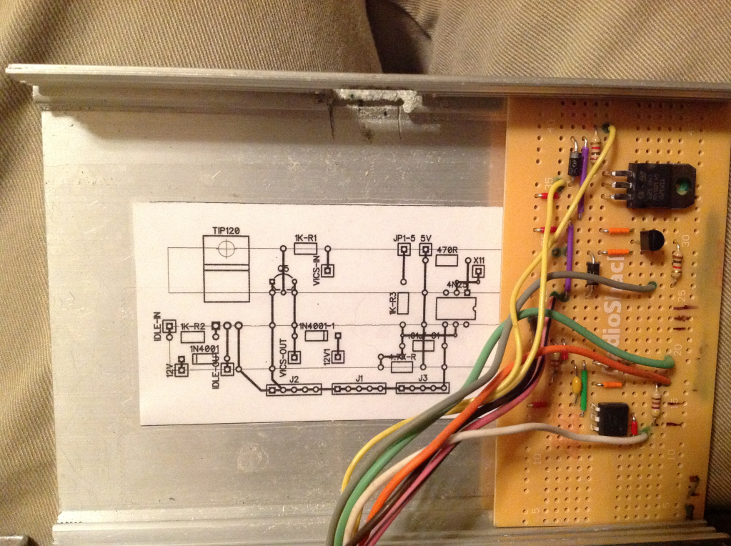
The TIP120 will be for controlling the idle valve, there is also a 4N25 which will likely be used for the crank/cam input signal. I'm not au fait with the V2.2 board though.
The TIP120 will be for controlling the idle valve, there is also a 4N25 which will likely be used for the crank/cam input signal. I'm not au fait with the V2.2 board though.
Reply
0
0
01-17-2014, 09:12 AM
#15
Boost Czar


iTrader: (62)
Join Date: May 2005
Location: Chantilly, VA
Posts: 79,493
Total Cats: 4,080
it's more than one circuit. The TIP120 is for idle, the VICs is controlled with that little transistor on Q5, and the integrated circuit appears to be a 4N25 so probably the cam input.
last time I put a TIP120 on a v2.2, I just put it on a standoff like this:
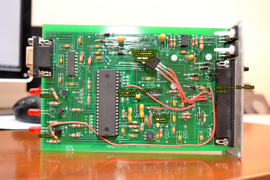
last time I put a TIP120 on a v2.2, I just put it on a standoff like this:
Reply
0
0
01-18-2014, 06:38 AM
#16
Junior Member
Join Date: Apr 2013
Location: Va
Posts: 87
Total Cats: -4
Yep a 2n2222 is there for the VICS (currently attached to the ms2 but not the db37)
The tip 120 is for idle control and the 4n25 opto is for the cam signal (I kept getting resets from the normal pull-up mod on the cam so I had to build this)
I designed the layout in a program called DipTrace and layed it out for a standard bread board setup that used a series of busses to keep everything neat.
I'm working on a DIY style breakout board that will incorporate these 3 small circuits so I can use the factory ecu case. Ill post up pics if anyone is curious.
Oh and to answer the question of "Why?" Posted above....simple
I'm cheep and had the ms2 and V2.2 board laying around. Next step will be making it sequential injection and fit in the factory ecu case (although I'm thinking I'm going to have to build my own pcb to stay in the small space and have sequential injection)
Last edited by Togeneral99; 01-18-2014 at 07:09 AM.
Reply
0
0

Thread
Thread Starter
Forum
Replies
Last Post
bigmackloud
Miata parts for sale/trade
19
01-08-2021 11:24 AM
StratoBlue1109
Miata parts for sale/trade
21
09-30-2018 01:09 PM


