problem: where to connect VTEC_Out
 04-13-2011, 03:39 PM
#1
Newb
Thread Starter

Join Date: Aug 2008
Posts: 12
Total Cats: 0
hello.
i have MS-1 pcb V3 with stand alone wiring.
and in its wiring is sticking out wire for VTEC_Out.
in this write-up is told:
Connect the VTEC_Out to your harness going to 1C.
this is my wiring:
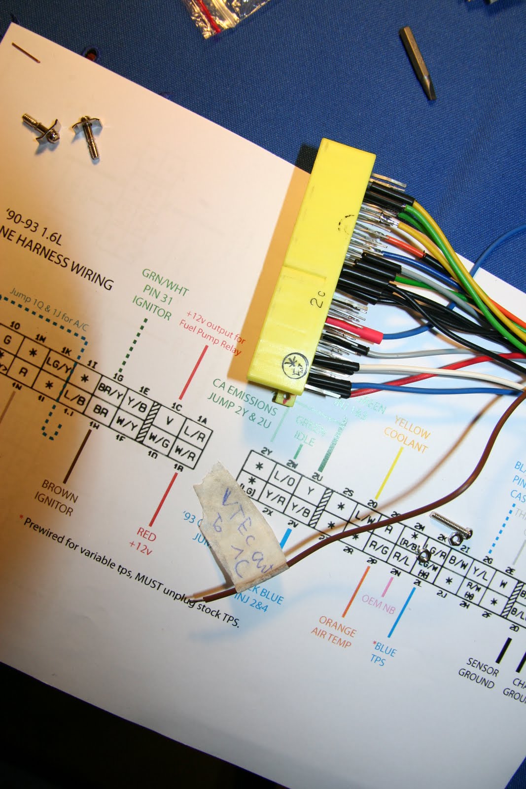
where should i solder that brown wire (VTEC_Out) to? to 1C in my connector?
but there already is a fuel pump wire(blue one).
sorry for my pour english.
i have MS-1 pcb V3 with stand alone wiring.
and in its wiring is sticking out wire for VTEC_Out.
in this write-up is told:
Connect the VTEC_Out to your harness going to 1C.
this is my wiring:
where should i solder that brown wire (VTEC_Out) to? to 1C in my connector?
but there already is a fuel pump wire(blue one).
sorry for my pour english.

Reply
 0
0

0
 04-13-2011, 04:14 PM
#3
Supporting Vendor


iTrader: (33)
Join Date: Jul 2006
Location: atlanta-ish
Posts: 12,659
Total Cats: 134
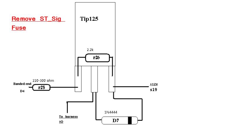
The schematic is labeled as it is because it was drawn up as a VTEC control circuit. I just hijacked the same circuit to use with a 90-93 Miata fuel pump.
"VTEC OUT FROM MS" would be your fuel pump output trigger and "TO VTEC SOLENOID" would be the lead to 1C.
"VTEC OUT FROM MS" would be your fuel pump output trigger and "TO VTEC SOLENOID" would be the lead to 1C.
Reply
0
0
04-14-2011, 02:57 PM
#4
Newb
Thread Starter
Join Date: Aug 2008
Posts: 12
Total Cats: 0
thanks for replies.
with VTEC_out to the wiring is done.
now, in my MS R16 is used for fuel pump. (i cant tell why, becouse I'm not the guy who assembled it)
so, to wich side of R16 I should solder the yellow wire?
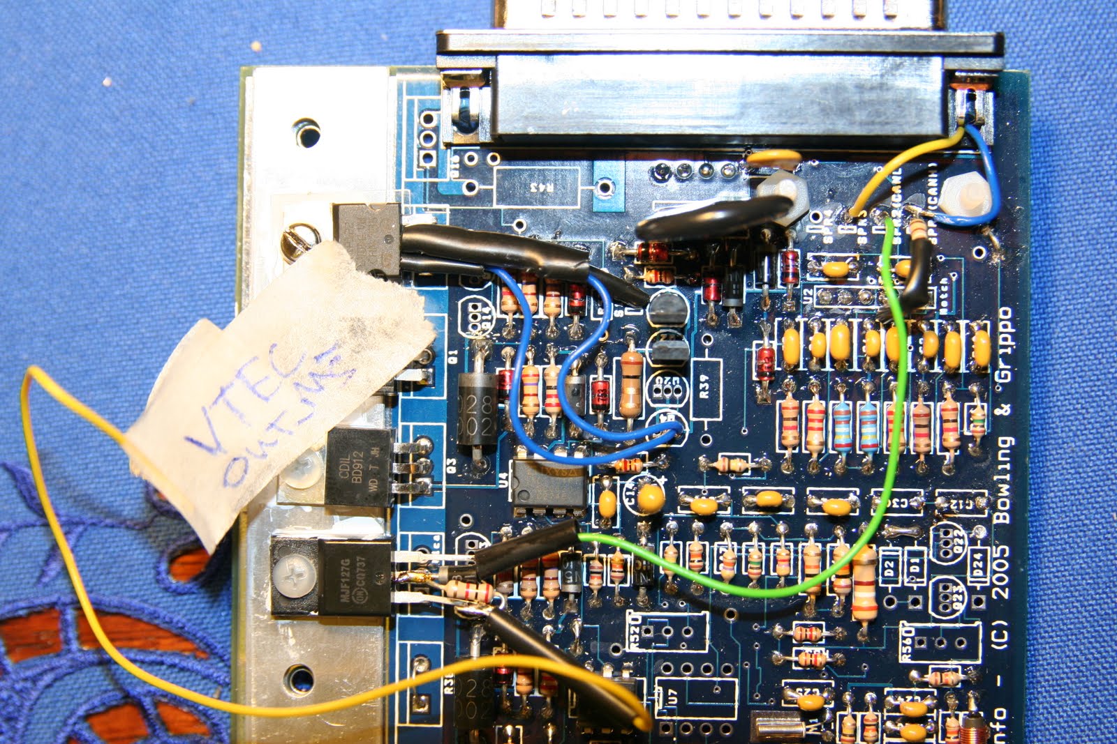
to the left side of R16?
with VTEC_out to the wiring is done.
now, in my MS R16 is used for fuel pump. (i cant tell why, becouse I'm not the guy who assembled it)
so, to wich side of R16 I should solder the yellow wire?
to the left side of R16?
Last edited by baronas_Lithuania; 04-15-2011 at 02:58 AM.
Reply
0
0
04-14-2011, 03:15 PM
#5
Boost Czar

iTrader: (62)
Join Date: May 2005
Location: Chantilly, VA
Posts: 79,494
Total Cats: 4,080
that's completely wrong. Look at the diagram I posted, that makes it too easy. You have the wires in the wrong spot and the diode is backwards.
Once you move the yellow wire to the correct lead on the transistor, you'll solder it to the banded end of D4, like the diagram says.
it also needs an insulator underneath it.
Once you move the yellow wire to the correct lead on the transistor, you'll solder it to the banded end of D4, like the diagram says.
it also needs an insulator underneath it.
Reply
0
0
04-19-2011, 03:43 AM
#6
Newb
Thread Starter
Join Date: Aug 2008
Posts: 12
Total Cats: 0
thank you for your help.
but this transistor ir tip 127, so everything is ok.
so I'v soldered yellow wire to D4 banded side and everything works
last night I'v tested my megasquirt, and my miata started with no problem, but it is working extreemly rich.
(my setup: Greddy turbo kit with 2.5"DP and 2.5" exhaust and stock injectors (ditched FMU). today I'm going to change injectors to Toyota Cellica 326cc.)
Reply
0
0
09-12-2011, 11:57 PM
#9
Boost Pope

iTrader: (8)
Join Date: Sep 2005
Location: Chicago. (The less-murder part.)
Posts: 33,027
Total Cats: 6,593
Sidebar: TIP125, eh? Any particular reason you didn't go for something like an AQV252?

Reply
0
0

Thread
Thread Starter
Forum
Replies
Last Post


