'99 MS3+MS3x No Start
 04-23-2016, 09:49 PM
#1
Senior Member
Thread Starter
iTrader: (1)

Join Date: Dec 2010
Location: Farmington Hills, MI
Posts: 1,218
Total Cats: 175
https://www.miataturbo.net/megasquir...g-sound-85634/
I'm getting the same exactly symptoms as the thread above, except no humming noise.
Backstory: '99 has been running on a DIYPNP for years and just switched to an MS3+MS3x V3.0. I built it using a combo of the assembly manual and Westfield MX5's manual. ID1000's, LS2 coils, pretty much everything else is stock.
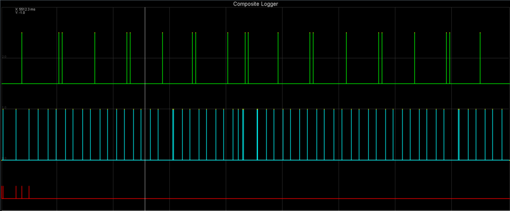
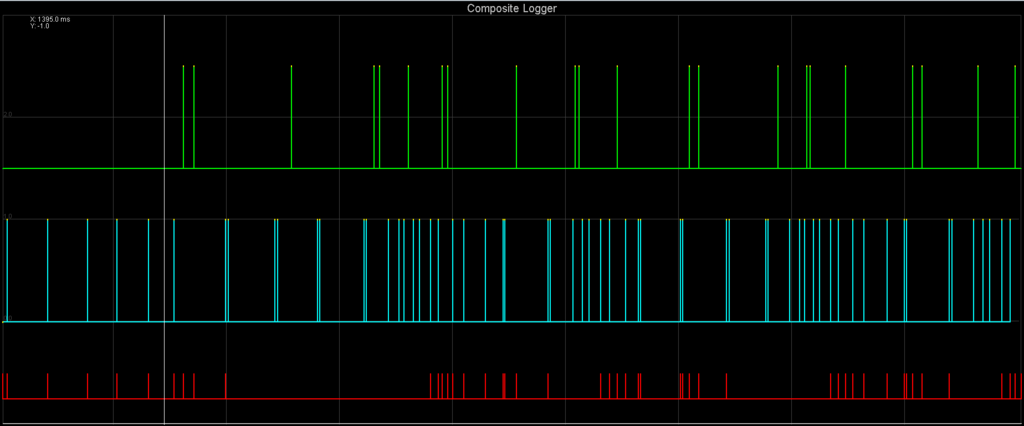
When I first tested cranking signal, I got a few counts of sync loss, then nothing after that. Checked again, no sync loss. No start, so I started tuning crank pw. It always had the weird popping noise as described in the thread above, so I knew something was up. Checked diagnostic tab and there was sync loss. A combo of 31 and 32 codes. Below are the evidence of good signal, then sync loss.
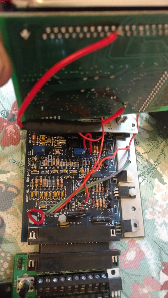
So I dug into the case, and checked voltages again on cam and crank circuits. Cam sensor sees 2.4V and cannot be adjusted higher. Crank sensor sees 2.8V. I saw in Franks guided that he installs a pullup between the left hole of R13 and right hole of R45. I have mine built to the manual with both R13 and R45 populated (and all other resistors for that matter). I also have the R52 pot populated instead of a fixed resistor. The jumpers I have in place go along with Franks guide. Pictures of my board are below.
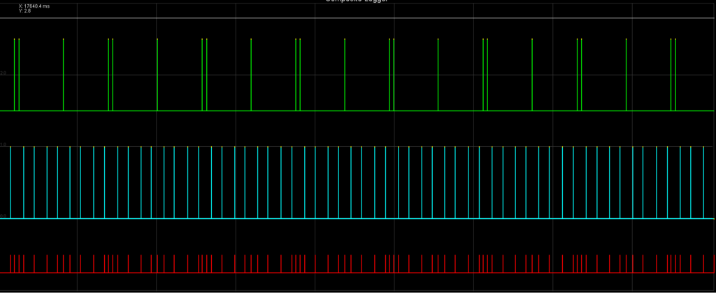
I then found the thread I linked to above (and the one linked to in that thread) and tried falling edge capture. It cranked smoothly (no popping) but there was a ton of sync errors and no RPM.
Any ideas? Thanks in advance.
I'm getting the same exactly symptoms as the thread above, except no humming noise.
Backstory: '99 has been running on a DIYPNP for years and just switched to an MS3+MS3x V3.0. I built it using a combo of the assembly manual and Westfield MX5's manual. ID1000's, LS2 coils, pretty much everything else is stock.
When I first tested cranking signal, I got a few counts of sync loss, then nothing after that. Checked again, no sync loss. No start, so I started tuning crank pw. It always had the weird popping noise as described in the thread above, so I knew something was up. Checked diagnostic tab and there was sync loss. A combo of 31 and 32 codes. Below are the evidence of good signal, then sync loss.
So I dug into the case, and checked voltages again on cam and crank circuits. Cam sensor sees 2.4V and cannot be adjusted higher. Crank sensor sees 2.8V. I saw in Franks guided that he installs a pullup between the left hole of R13 and right hole of R45. I have mine built to the manual with both R13 and R45 populated (and all other resistors for that matter). I also have the R52 pot populated instead of a fixed resistor. The jumpers I have in place go along with Franks guide. Pictures of my board are below.
I then found the thread I linked to above (and the one linked to in that thread) and tried falling edge capture. It cranked smoothly (no popping) but there was a ton of sync errors and no RPM.
Any ideas? Thanks in advance.

Reply
 0
0

0
04-23-2016, 10:27 PM
#2
Senior Member
iTrader: (1)

Join Date: Sep 2011
Location: Lambertville, NJ
Posts: 1,215
Total Cats: 74
You just may have flooded the engine. Go back to rising edge, Lower cranking PW by maybe 20%. Crank and after a few seconds floor the loud-pedal to go into flood-clear.
Reply
0
0
04-23-2016, 10:59 PM
#3
Senior Member
Thread Starter
iTrader: (1)
Join Date: Dec 2010
Location: Farmington Hills, MI
Posts: 1,218
Total Cats: 175
I started at 100% and slowly went upwards in PW. Then went back down and flood cleared several times. Even when constant flood clearing, the popping sound still happens..
Forgot map and log earlier.
Forgot map and log earlier.
Reply
0
0
04-24-2016, 09:39 PM
#6
Senior Member
Thread Starter
iTrader: (1)
Join Date: Dec 2010
Location: Farmington Hills, MI
Posts: 1,218
Total Cats: 175
I tried setting up my 5V pullup like Frank (1k resistor from left leg R13 to right leg R45). Same results as before. Cam and crank signals are coming in, but constant sync loss and no rpm.
Reply
0
0
04-25-2016, 07:16 AM
#7
Boost Czar


iTrader: (62)
Join Date: May 2005
Location: Chantilly, VA
Posts: 79,494
Total Cats: 4,080
yeah that's not the problem, youre getting the singals in just fine, but the look look off for something reason, the MS is expecting the signals is slightly different spots than what you're seeing. I'd say your timing if off, but you said it was running the DIYPNP just fine.
Reply
0
0
04-25-2016, 08:04 PM
#8
Senior Member
Thread Starter
iTrader: (1)
Join Date: Dec 2010
Location: Farmington Hills, MI
Posts: 1,218
Total Cats: 175
I was hoping it'd be a firmware issue, so I flashed the new 1.4.1. Same condition. Is there any possible way the MS3 would desire a much different trigger offset than the DIYPNP, which is causing the signals to show up in different spots?
Reply
0
0
04-26-2016, 06:40 PM
#9
Senior Member
Thread Starter
iTrader: (1)
Join Date: Dec 2010
Location: Farmington Hills, MI
Posts: 1,218
Total Cats: 175
I believe the issue is solved. I had my trigger offset set to 10 degrees, as I did with the DIYPNP. Changed it to 0 and it fired right up. Unfortunately I didn't have the map sensor connected (because I've been taking it in and out a hundred times) so it died right away, and my battery is too dead to check for consistent good signal. But it does make sense that the trigger offset would be different on a rising edge to falling edge setup.
Reply
0
0

Thread
Thread Starter
Forum
Replies
Last Post


