MEGAsquirt A place to collectively sort out this megasquirt gizmo

Second optoisolator on MS2

Thread Tools
 
Search this Thread
 
Old 04-08-2013, 04:42 PM
  #61  
Junior Member
Thread Starter
iTrader: (1)
 
duffbuster243's Avatar
 
Join Date: Sep 2010
Location: Scranton PA
Posts: 264
Total Cats: 4
Default

Ok false alarm. It seems that my crank pulley has slipped on its rubber isolator, Time for a new one I guess.
duffbuster243 is offline  
Old 04-09-2013, 08:46 AM
  #62  
Boost Czar
iTrader: (62)
 
Braineack's Avatar
 
Join Date: May 2005
Location: Chantilly, VA
Posts: 79,508
Total Cats: 4,080
Default

time for a 1.8L!
Braineack is offline  
Old 04-09-2013, 09:32 AM
  #63  
Junior Member
Thread Starter
iTrader: (1)
 
duffbuster243's Avatar
 
Join Date: Sep 2010
Location: Scranton PA
Posts: 264
Total Cats: 4
Default

The 1.6 Is built with b6t connecting rods and 9.0:1 compression pistons. I don't plan on going 1.8 any time soon.
duffbuster243 is offline  
Old 04-13-2013, 07:58 PM
  #64  
Boost Czar
iTrader: (62)
 
Braineack's Avatar
 
Join Date: May 2005
Location: Chantilly, VA
Posts: 79,508
Total Cats: 4,080
Default

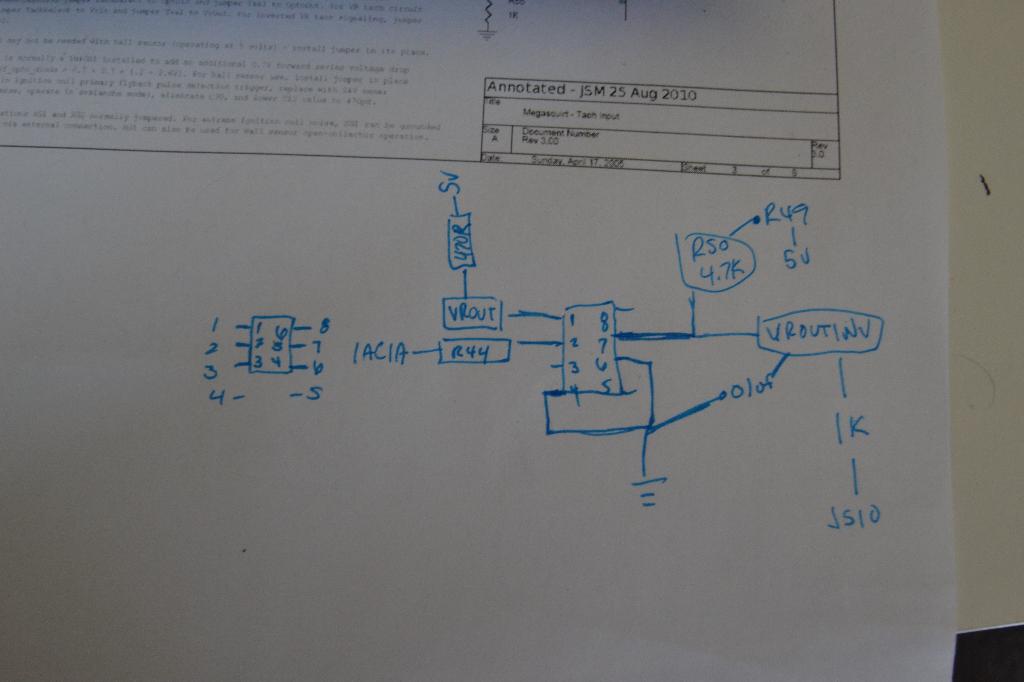
I'm upgrading a MS2 to MS3, decided to add the second opto just as a precaution, although this has been running fine on ms2 since 2008 with just the pull-up on js10.


Attached Thumbnails Second optoisolator on MS2-dsc_6194.jpg   Second optoisolator on MS2-dsc_6195.jpg   Second optoisolator on MS2-dsc_6196.jpg  

Last edited by Braineack; 04-14-2013 at 11:12 AM.
Braineack is offline  
Old 04-14-2013, 11:12 AM
  #65  
Boost Czar
iTrader: (62)
 
Braineack's Avatar
 
Join Date: May 2005
Location: Chantilly, VA
Posts: 79,508
Total Cats: 4,080
Default

I made a slight error when I built the circuit. I used the wrong hole for r49 so I was sending 5v to ground. I'll post new pics in a sec.

here's what I did:
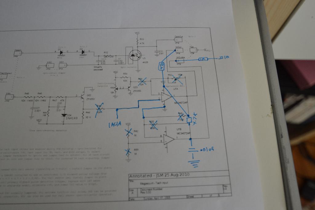


syncs perfectly.
Attached Thumbnails Second optoisolator on MS2-dsc_6201.jpg  

Last edited by Braineack; 04-14-2013 at 11:34 AM.
Braineack is offline  
Old 04-14-2013, 05:31 PM
  #66  
Senior Member
 
WestfieldMX5's Avatar
 
Join Date: Nov 2007
Location: Belgium
Posts: 999
Total Cats: 73
Default

Here's how I'm doing mine. FWIW


Last edited by WestfieldMX5; 04-28-2013 at 02:10 PM.
WestfieldMX5 is offline  
Old 04-15-2013, 06:17 AM
  #67  
Junior Member
iTrader: (2)
 
zipstrips's Avatar
 
Join Date: Dec 2009
Location: scranton, pa
Posts: 103
Total Cats: 5
Default

thanks for putting some leg work for our Ms2's duff! cant wait to drive without that sync loss we have seen.
zipstrips is offline  
Old 04-15-2013, 08:05 AM
  #68  
Boost Czar
iTrader: (62)
 
Braineack's Avatar
 
Join Date: May 2005
Location: Chantilly, VA
Posts: 79,508
Total Cats: 4,080
Default

Originally Posted by WestfieldMX5
Here's how I'm doing mine. FWIW
It was because of you I tried doing it into a preexisting circuit, otherwise I'd have just done it on the proto.

I probably spent a good 2 minutes coming up with it and going gung-ho, I probably could have put more thought into it and made it cleaner, but i just didn't really care that much

Last edited by Braineack; 04-15-2013 at 04:38 PM.
Braineack is offline  
Old 04-15-2013, 04:35 PM
  #69  
Senior Member
 
WestfieldMX5's Avatar
 
Join Date: Nov 2007
Location: Belgium
Posts: 999
Total Cats: 73
Default

I probably have to much free time
WestfieldMX5 is offline  
Old 04-15-2013, 04:53 PM
  #70  
Junior Member
Thread Starter
iTrader: (1)
 
duffbuster243's Avatar
 
Join Date: Sep 2010
Location: Scranton PA
Posts: 264
Total Cats: 4
Default

I used one of these: Dual General-Purpose IC PC Board : PC Boards | RadioShack.com cut in half, and bolted it on to the bottom of the MS board using a previously unused hole in the heatsink.
duffbuster243 is offline  
Old 04-16-2013, 02:24 PM
  #71  
Elite Member
 
JasonC SBB's Avatar
 
Join Date: Jul 2005
Posts: 6,420
Total Cats: 84
Default

Westfield, what are you trying to do with U7A? The majority of comparators' valid input range is VCC-1.5V. You are connecting its inverting input to VCC.
JasonC SBB is offline  
Old 04-16-2013, 02:50 PM
  #72  
Boost Czar
iTrader: (62)
 
Braineack's Avatar
 
Join Date: May 2005
Location: Chantilly, VA
Posts: 79,508
Total Cats: 4,080
Default

mirroring the circuit above, for the ckp, using the same 4n25 as seen on u3 in the U7A spot.

Attached Thumbnails Second optoisolator on MS2-2ndcas_input.gif  
Braineack is offline  
Old 04-16-2013, 05:54 PM
  #73  
Senior Member
 
WestfieldMX5's Avatar
 
Join Date: Nov 2007
Location: Belgium
Posts: 999
Total Cats: 73
Default

Like he said î
Same as Scott's, but in my drawing U3 goes in the lower 6 holes of the U7 location. Scott is using the upper holes.
WestfieldMX5 is offline  
Old 04-17-2013, 12:22 AM
  #74  
Boost Pope
iTrader: (8)
 
Joe Perez's Avatar
 
Join Date: Sep 2005
Location: Chicago. (The less-murder part.)
Posts: 33,076
Total Cats: 6,628
Default

Originally Posted by WestfieldMX5
Scott is using the upper holes.
I know for a fact that Scott prefers the lower hole.
Joe Perez is offline  
Old 04-17-2013, 01:28 AM
  #75  
Elite Member
 
Zaphod's Avatar
 
Join Date: Mar 2006
Location: Schwarzenberg, Germany
Posts: 1,554
Total Cats: 101
Default

Originally Posted by Joe Perez
I know for a fact that Scott prefers the lower hole.
Dammit, now I spilled all the Coffee into my keyboard...
Zaphod is offline  
Old 04-17-2013, 02:05 AM
  #76  
Elite Member
 
JasonC SBB's Avatar
 
Join Date: Jul 2005
Posts: 6,420
Total Cats: 84
Default

Are you using a comparator symbol to denote an opto?
JasonC SBB is offline  
Old 04-17-2013, 08:55 AM
  #77  
Boost Czar
iTrader: (62)
 
Braineack's Avatar
 
Join Date: May 2005
Location: Chantilly, VA
Posts: 79,508
Total Cats: 4,080
Default

Originally Posted by JasonC SBB
Are you using a comparator symbol to denote an opto?
no? but I drove the car to work today.

Braineack is offline  
Old 04-07-2015, 03:49 PM
  #78  
Newb
 
Zhimin90's Avatar
 
Join Date: Jun 2014
Posts: 18
Total Cats: 0
Default

Originally Posted by Braineack
mirroring the circuit above, for the ckp, using the same 4n25 as seen on u3 in the U7A spot.

Reviving the dead. Im running into issues with cam signal disappearing while cold crank or driving at low rpm randomly. Seems like either I can do this for cheap or try a new cam sensor. The choice look pretty obvious.

The problem is I am running DIYPNP V1.53B board, so these pins don't apply to me. I couldn't find the schematic for the V1.53B board so its pretty hard to see what is going on. I read somewhere the cam signal is fed directly to the CPU with only pull a 5 volt pullup.

So, I am going to build this on the proto area completely. From what I read so far, I should be able to use this circuit and feed it into the VR2+ the cam input without the pullup to 5V attached to VR2+.

For your convenience. Here is the pin out for DIYPNP board for 95 miata which is what Im driving.
DIYPNP MegaSquirt installation for the Mazda Miata
Zhimin90 is offline  
Old 04-07-2015, 06:15 PM
  #79  
Boost Czar
iTrader: (62)
 
Braineack's Avatar
 
Join Date: May 2005
Location: Chantilly, VA
Posts: 79,508
Total Cats: 4,080
Default

youre having drop out on a DIYPNP?

post the composite log to prove it.

how did you do you pull ups?
Braineack is offline  
Old 04-07-2015, 08:03 PM
  #80  
Newb
 
Zhimin90's Avatar
 
Join Date: Jun 2014
Posts: 18
Total Cats: 0
Default

Originally Posted by Braineack
youre having drop out on a DIYPNP?

post the composite log to prove it.

how did you do you pull ups?
08.csv has dropout at 149/157
15.csv is at 112/153 and 58/153

I did the pull up according to the DIY PNP websites table for 94/95(VR2 to 470 resister pulled to 5v with R20 and r21 r39 open.
Attached Files
File Type: csv
2015-04-04_15.02.08.csv (1.73 MB, 93 views)
File Type: csv
2015-04-04_17.32.15.csv (1.68 MB, 79 views)
Zhimin90 is offline  


Quick Reply: Second optoisolator on MS2


All times are GMT -4. The time now is 07:18 AM.