When you click on links to various merchants on this site and make a purchase, this can result in this site earning a commission. Affiliate programs and affiliations include, but are not limited to, the eBay Partner Network.
Time For My Build Thread! Boosting on a Budget: Greddy Kit Done *Right*
A few things before we get started... I am a 19 year old college student from Saint Louis, Mo. I currently attend Truman State University studying Marketing, Finance, and Economics. I've recently been scratching the surface of electrical engineering- fun stuff! I plan on this being a build thread/blog post/marketing experiment hybrid all wrapped into one.
Anyway, let's get to the fun part!
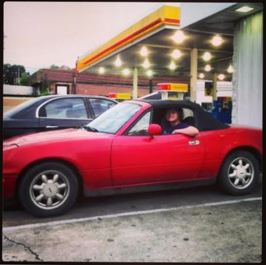
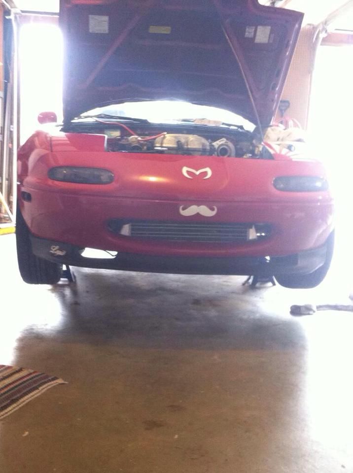
I purchased my bone stock 1990 1.6 Miata with just over 137K on the clock for $1,400 in late April of 2013 after a four month long bartering adventure via Craigslist. Essentially, I turned a crappy old ping pong table into my beautiful roadster that I have today; But that story is for a different thread...
Here we are about to make our 8 hour journey home. I bought the car from farmland Kentucky which is where it spent its whole life (Minimal rust issues- Woo!) I had to make it back home in time to get some rest before school the next day. Couldn't miss out on AP Chemistry now could we?!
After almost two years of maintenance, fitting some basic performance parts (intake, full exhaust, suspension), I decided that it was time for boost. I had been toying around with the idea for almost a year at this point and finally pulled the trigger on the first purchase.
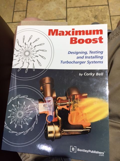
I would recommend reading this book before buying anything. It's extremely informative and a good read.
I had done research on engine management for a while and knew that if I was going to do this then I should do it the right way and go with a full standalone unit. Don't go around this, it's worth it. You will appreciate how expandable and tune-able standalone units are over piggybacks and band-aids later. Trust me.
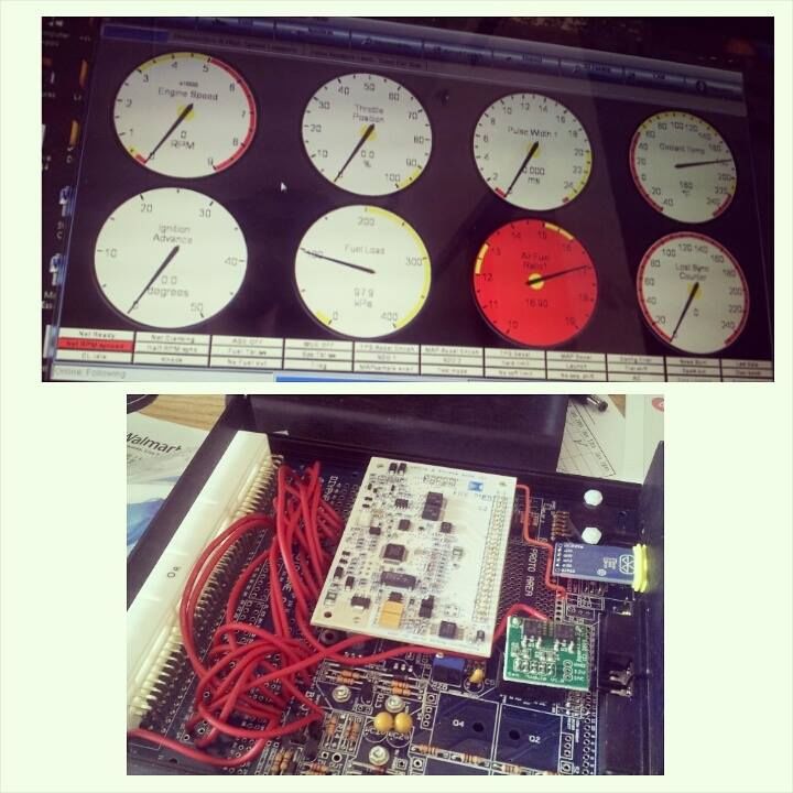
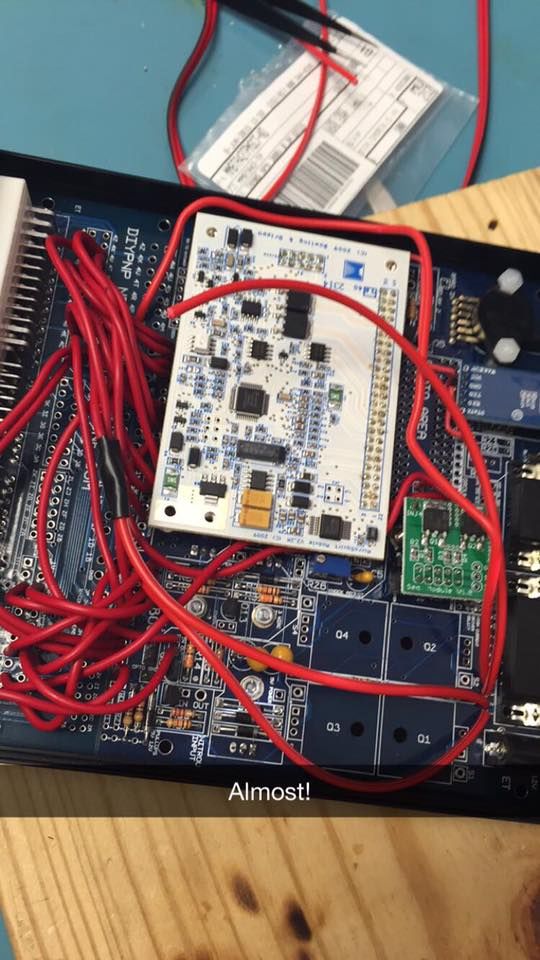
I got a sweet deal on a MS2 DIYPNP from a guy online who made it for a customer of his who backed out. Picked it up for $525 shipped. Looking back on this now, I kind of wish that I would have assembled my own board because, you know, pride in craftsmanship. Maybe some day.
Loading the appropriate firmware onto my board and staring in awe of Tuner Studio and its many features.
Pro Tip: Buy the registered version of both Tuner Studio and Mega Log Viewer. They're worth it. Pro Tip 2: These DB-9 connectors are finicky with BAUD rates and such. Buy the USB to DB-9 connector from http://http://www.diyautotune.com/ to guarantee solid communication between your ECU and computer.
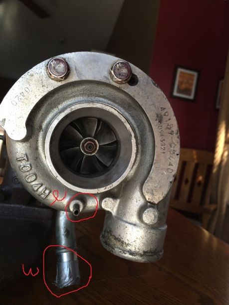
I was on a vacation with my dad in California to tear up the ocean-side sand dunes on some 4 wheelers. I did a quick Craigslist search just for the hell of it and actually found a solid deal that I just had to jump on. I bought a Greddy TD04H turbocharger, Greddy cast iron manifold, Greddy downpipie, universal JDM Sport intercooler kit, and oil supply line for $465 from a kid who didn't have enough patience to DIY-turbo himself.
My knowledge of turbos was embarrassingly minimal, so I emailed some pictures to Stephanie at BEGI to get help with figuring out what was what.
The whole team at Bell Engineering has been highly supportive throughout my whole build. I really appreciate their outstanding customer service and the high quality of the parts they provide.
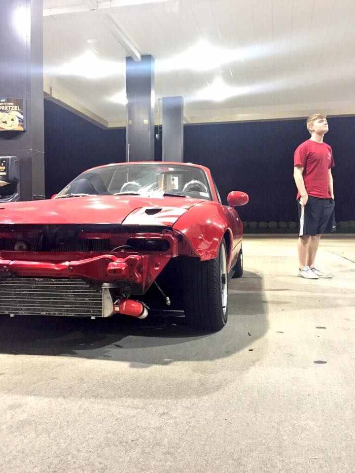
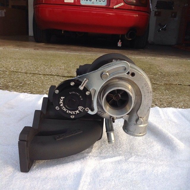
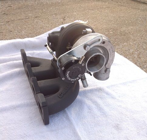
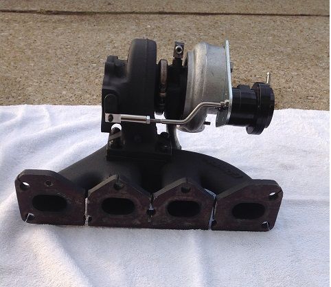
Getting ahead of myself here but this is what the manifold and turbo ended up looking like
Pismo Beach sand dunes! Definitely a fun time.
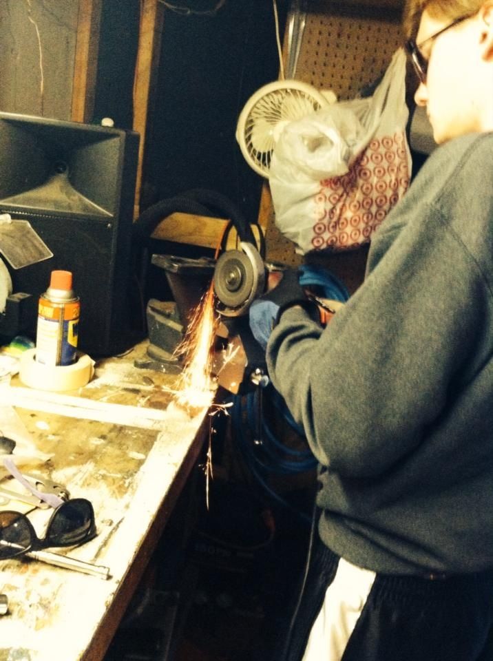
Everyone that runs these Greddy cast manifolds seemed to like the idea of making relief cuts in them so I went ahead and got the angle grinder out and made some on mine as well. I probably should have used a band saw, but the angle grinder worked okay.
Making the relief cuts in the manifold
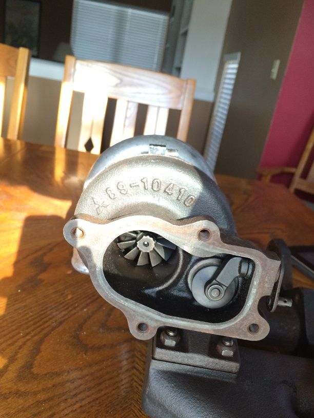
I removed the turbo from the manifold in order to clock the compressor housing and give it a good cleaning while I was at it- Mineral spirits worked well for me. I gave the manifold and exhaust housing a few coats of high temperature flat black paint.
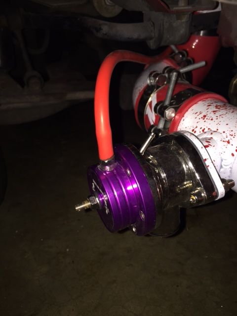
I also installed my adjustable wastegate actuator. Don't forget the cotter pin! It will come off from the wastegate flapper door and you will burn your finger frantically trying to get it back on some night while you're taking some datalogs.
I went with the 7.35 pound spring option from Kinugawa for $105. It has a great finish and is an all-around solid product.
Finished product!
After the long MLK weekend, it was time for me to go back to school for about two more months. I took this time away from the car to do some more research on the forums in attempt to figure out some intercooler routing ideas and (try to) start learning about tuning... I have only recently found some success with this.
Spring Break came soon enough and I got some more solid work done on the car. I removed all of my old exhaust and some of my intake parts. For first timers- PB Blaster is your friend! I also had to rotate my wastegate actuator so I could run a cleaner reference line to the compressor housing. I also removed the air conditioning and power steering (de-powered the rack) to ease the task of routing IC piping. And for some mad power gains/weight reduction.
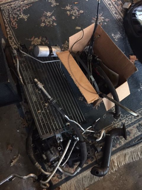
Removing the AC: This job is pretty straight forward. Unbolt the compressor from the block, unbolt the condenser from the car, and remove all of the AC lines and hoses in the engine bay. You can also remove the evaporator box that is behind the glove compartment and install a crossover tube for a totally complete AC removal. I just uninstalled all of the components in the engine bay, however, and have not had any problems.
I estimated a weight reduction of around 40 pounds by getting rid of all of this junk. Notice the Greddy downpipe in the junk pile.
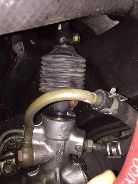
Removing the PS: There are a few ways to do this. The *best* way to do this would be to buy a manual steering rack and completely replace the power steering unit that you have in your car. I just chose to de-power my steering rack. There are a few ways to do this as well... The *best* way to do this would be to follow the write up by Fyin' Miata here: https://www.flyinmiata.com/tech/depower.php. This method entails totally disassembling the steering rack and removing all of the seals inside.
I went the super DIY route with mine and just removed the PS pulley from the block, removed the reservoir and its lines, and then looped the lines inlet and outlet lines from the rack itself. When doing it this way, it is important to bring your steering wheel to full lock, both ways a few times with the lines disconnected to drain the rack from most of its fluid. You still want some fluid within the rack, though, to keep the inside of itself lubricated.
Here is how I looped my lines.
We also started started on fabbing up a custom downpipe because there is absolutely no way that I was going to run the garbage that Greddy called a downpipe. I decided on going with a 2.5" turbo-back setup. I'd recommend going with a 3" setup, though. I will be upgrading to 3" next time I run out of other things to work on.
First mock up the manifold and turbo. Looks pretty good! Err... I removed the AC and PS after I took this pic.
Sorta getting an idea of how the car will look with an intercooler
Met some pretty cool people and made some good friends during the build process, too, so that was pretty awesome.
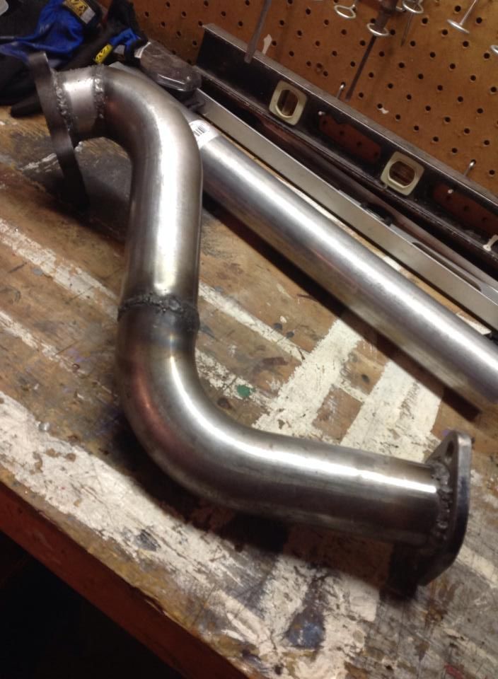
Finished downpipe! We had to add an inch of pipe between the exhaust housing flange and where we began the curve downward in order to have room for the bottom bolt on the flange.
Off to school again... I took this time away from my car to order some of the parts that I have been holding off on buying that include the following:
T-bolt clamps- $30
Mishimoto couplers- $100
Glowshift boost gauge- $35
NGK 4644 (BKR7E) spark plugs- $9
RX-7 460cc Red Top fuel injectors- $50
Hallman Pro manual boost controller- $35
Innovate MTX-L wideband O2 sensor- $165
New gaskets for both sides of the turbo- $15
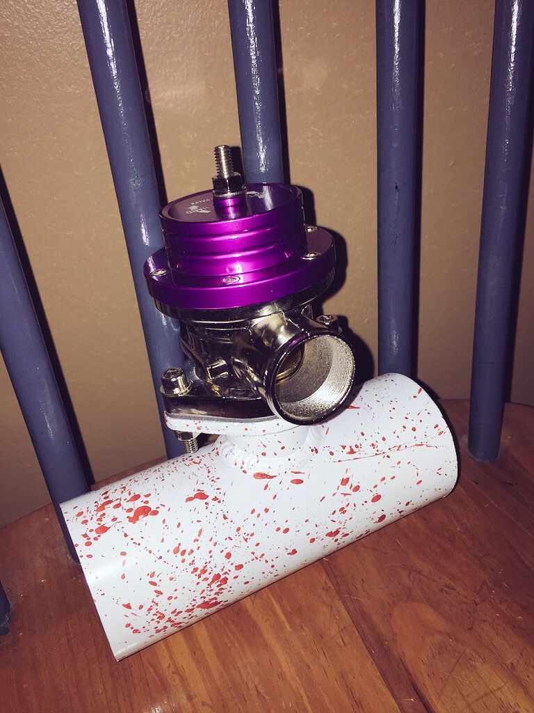
Greddy RS-Style blow off valve and flange pipe- $50
3mm and 4mm Silicone boost/vac/reference lines- $30
Oil return line and oil pan bit/tap/fitting from BEGI- $35 (I sold the bit and tap for the $28 I paid for them)
Here's a shot of my MBC installed. Make sure you hook up the reference lines correctly or you'll have a bad time.
Note: It's fairly common to experience "boost sag" which is basically when you start losing boost after you start holding max boost. (Ex: Your wastegate is set at 7 psi. You build up to 7 psi and hold off on shifting for a few seconds. You begin to loost boost pressure). This can be remedied by routing the compressor housing reference line to the cold side of the intercooler. There's reason behind this that is detailed in another thread. Mine is functioning properly for now, however, so I will address that if/when it becomes an issue. Joe's thread on here explains this in greater detail: https://www.miataturbo.net/diy-turbo...eed-ebc-47532/
I also re-routed my crankcase filter elsewhere with the use of a factory tube and hose in order to gain clearance for the wastegate. I'll be upgrading to an oil catch-can setup soon.
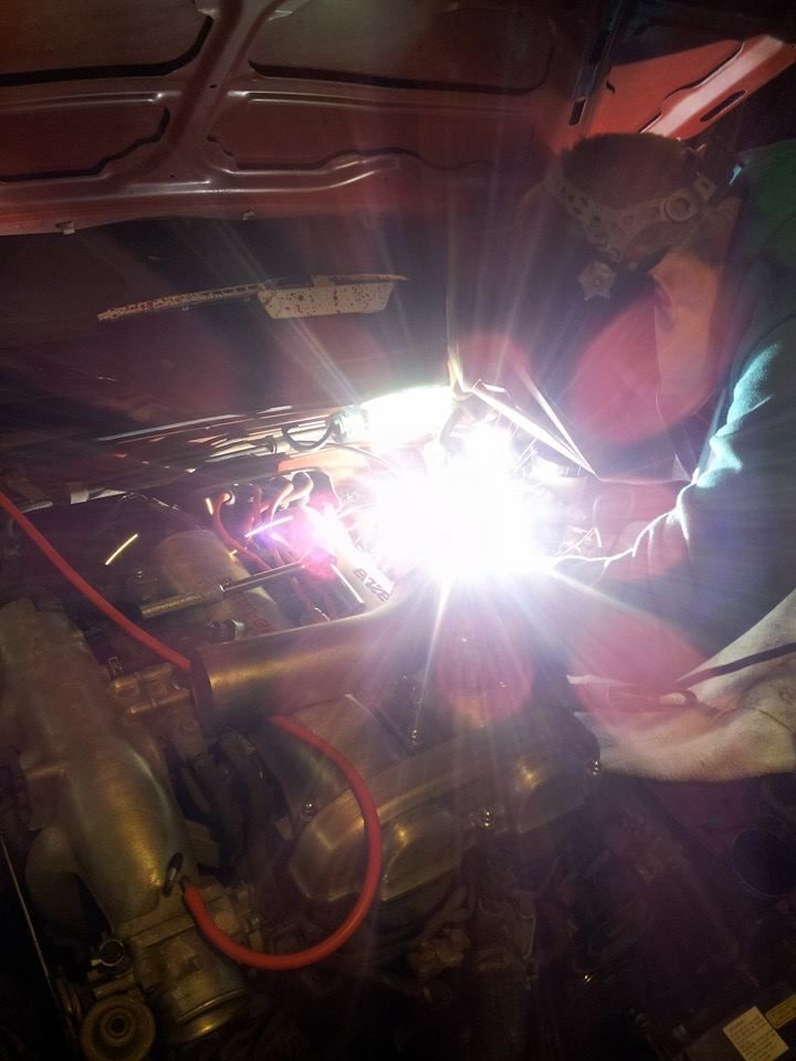
My next long weekend came at the beginning of April and this is when I felt that I made some real progress. We finished fabbing up the rest of the exhaust. I currently have a 2.5" catless turbo-back setup that's dumped at the differential. I'm still thinking about exhaust exit ideas... Classy or JDM? Hmm. I even tested the waters with welding myself! I ended up having my buddy go back over the hangar weld because I didn't trust my weld to hold up... Again, maybe some day
More exhaust work...
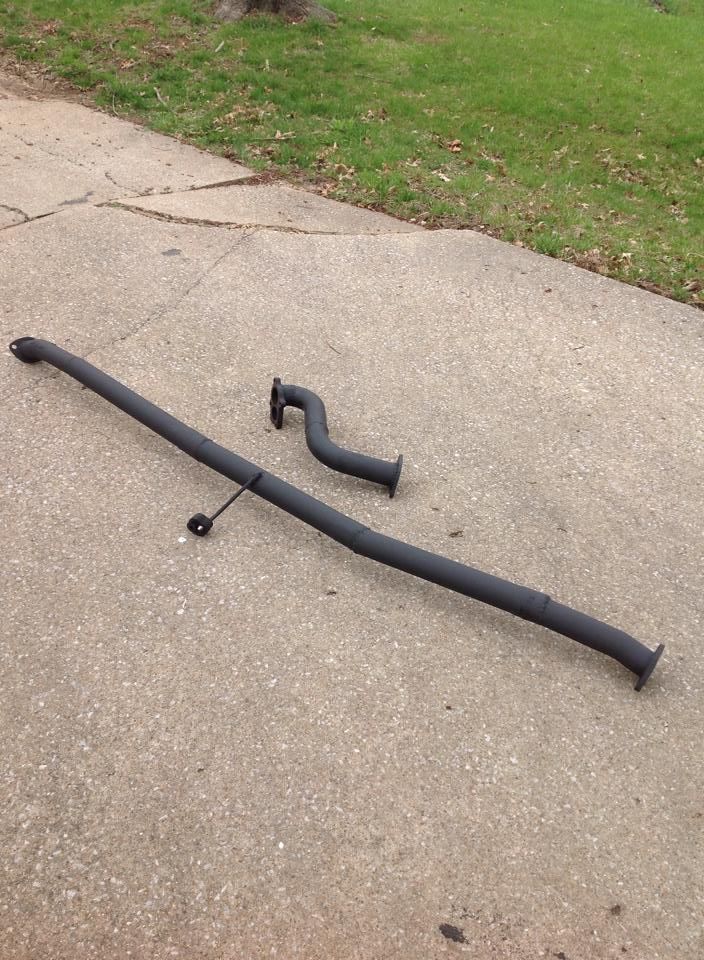
Finished exhaust setup! I currently have it dumped at the diff but will be fabbing up a fun exit pipe soon.
I took some time to straighten out the fins on the intercooler the best I could. I also cleaned it out with acetone by rubber banding Target bags on inlet and outlet and swished it around and then flushed it out.
Acetone works really well because it evaporates very quickly- Just try not to get too much of it on you! Repeat the process until nothing but clear liquid is coming out.
The cleaned intercooler and some custom brackets to hold it in place
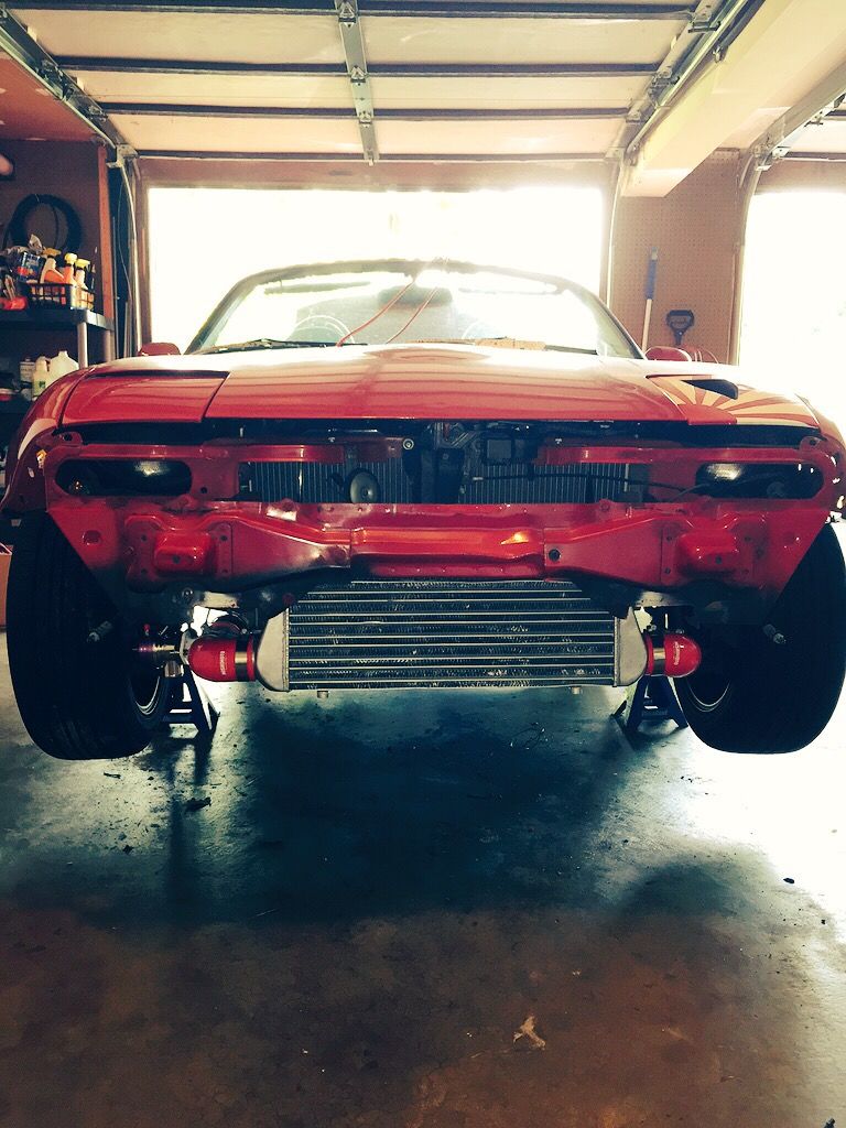
Mocking up up the intercooler and piping actually turned out to be a bit more of a chore than I originally anticipated it to be. But after a few long nights and some creativity, I finally got it all mocked up with the help of some friends.
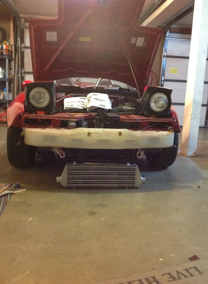
The intercooler stays in place all by itself. "Look Mom, no jack stands!" Brief install of the bumper cover to see what she'll look like when this is all over with
And with that long weekend over with, I had to push through one more month of University. I didn't have too much time to worry about much of the turbo build because I had my sister's wedding coming up so I was busy trying to get all of my final projects, papers, and presentations finished up.
Finals were coming the week after so I had to have a clean slate for my studying, late nights, and unhealthy amounts of energy drinks and junk food.
Some pictures from the wedding rehearsal- My girlfriend, sister, and new brother-in law: Just a fraction of the great support team I have!
The end of the first week in May marked the end of my first year of college. I survived. I even found time to make some new friends, have some great experiences, and earn some solid grades.
(continued in next post)
Last edited by typicalsteve; Jun 30, 2015 at 08:55 PM.
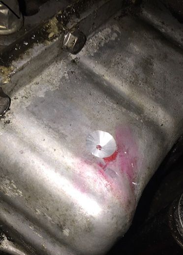
The next step was to finally drill and tap the pan. This is the part of this whole project that I think I had the most anxiety. After getting it done, however, I realized that it's really not THAT bad. For anyone considering removing the pan before tapping it; Don't. Flyin' Miata, BEGI, and most everyone on the forums agree that it is best to just do the job with the pan on the car. Unless you already have the motor out of the car for whatever reason, don't bother with removing the pan.
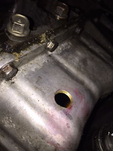
I used a 37/64" drill bit and a 3/8" NPT tap to drill and tap the pan. I then installed a 3/8" NPT to 5/8" hose barb brass adapter fitting in place.
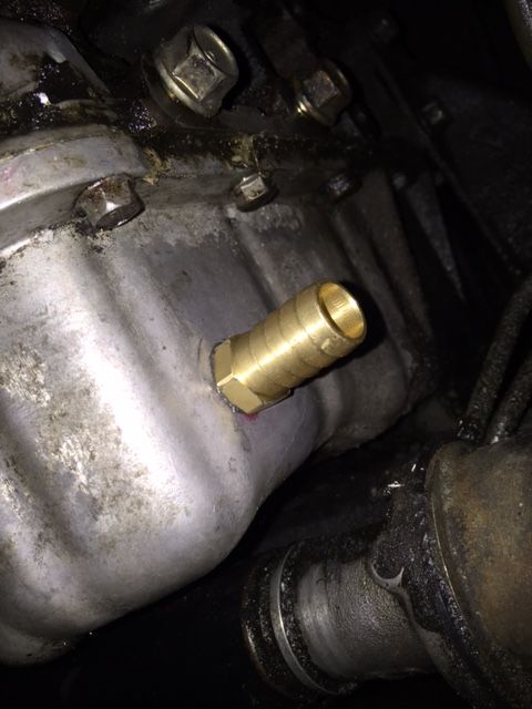
And the fitting in place! I used black RTV to seal the threads and haven't had any issues so far.
I wanted take a break from mechanical stuff after tapping the oil pan because I felt like I had just cleared the toughest obstacle of the build. Whew!
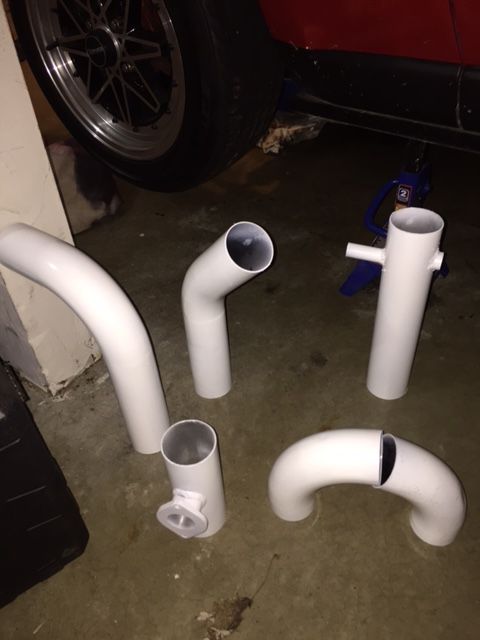
So I got creative and went on to painting the intercooler piping. I couldn't justify spending $100 on couplers without having piping then coordinated with them. I also couldn't justify spending $250 on getting these pipes professionally powder coated as I wasn't entirely sure on the color scheme yet.
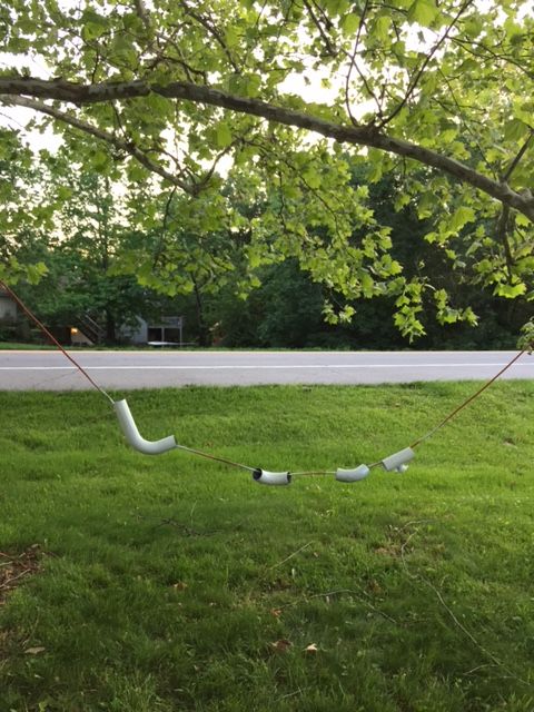
I found that stringing the pipes on and old extension cord and suspending them from a tree branch was the best way to ensure full, even paint coverage.
Caveat: This painting method will cause some weird looks by passersby
Base coats finished. Also welded on an extension for my IACV and a bung for IAT sensor to the pipe coming from my throttle body
Couldn't forget the red splatters to match my wiper blades and tow hooks!
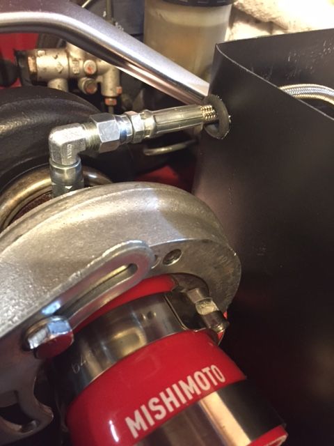
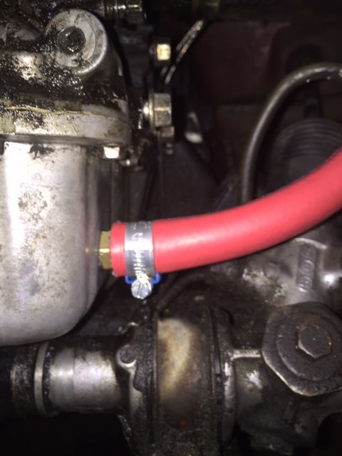
Next up was to supply the turbo with some oil. The 1.6 block conveniently has an unused port that can be used for the supply tap. After struggling with trying to find the proper fittings to install my oil supply line that came with everything I bought from the guy in Anaheim, I finally decided to switch from that -3AN line to a -4N line from BEGI.
A note about oil supply lines- Having one that is a custom length for your specific setup is ideal. Having less slack in the oil supply line will give you a cleaner setup and decrease the chance of it chafing against something and ultimately failing. Running loops in oil supply lines is OK according to the guys at two of my local performance automotive shops. Personally, I wouldn't, though.
I highly recommend their oil supply line kit. It comes with high quality stainless steel fittings and adapters for a solid price. I sourced my oil restrictor fitting from Kinugawa because this Greddy turbocharger calls for a 1.5mm (0.060") restrictor and Bell only had Garrett restrictors on hand at the time (Usually 1mm or 0.030-0.032").
Overview of my supply line installed. I ran it through my custom intake isolation box and protected it from chafing with a pair of grommets.
The Greddy TD04H oil supply inlet has an M10x1.25 thread pitch. My oil restrictor doubled as the M10x1.25 to -4AN adapter fitting.
The 1.6 block oil supply inlet has an M10x1.5 thread pitch. BEGI took any guess work out for me, though.
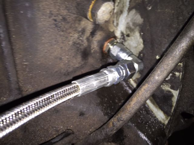
A note about oil drain lines- You want them to be as smooth as you can make them. Avoid kinking the line or routing it with a bunch of intricate curves. They are gravity fed so they need to be a straight shot into the oil pan.
Turbo drain barb to oil drain hose- Make sure these clamps are tight!
Notice the nice and smooth flow of the drain line
Gotta give more props to BEGI for these fancy hose clamps that prevent you from cutting into the hose by when tightening them down!
I then gave everything in the engine bay a hard and *final* install. I had all of my hot parts taken back off to ease with the oil supply line installation. After taking these parts on and off more times then I would like to, I found that this is the order of which installing each part proved to be most effective:
1. Bolt exhaust housing to manifold. Make sure these nuts are tight.
2. Bolt manifold to block. Make sure these nuts are tight.
3. Install O2 sensor into downpipe. Make sure it is tight.
4. Bolt downpipe to exhaust housing. Make sure these bolts are tight.
5. Clamp compressor housing to exhaust housing. Make sure the bolt is tight.
6. Connect actuator to wastegate flapper door. Make sure this is very tight so it will hold your boost. Again, don't forget the cotter pin.
During and After your installation process, MAKE SURE YOUR BOLTS/NUTS/CONNECTIONS ARE TIGHT. Exhaust leaks cause boost leaks, inaccurate AFR reading, and cancer. All of which are frustrating and no fun.
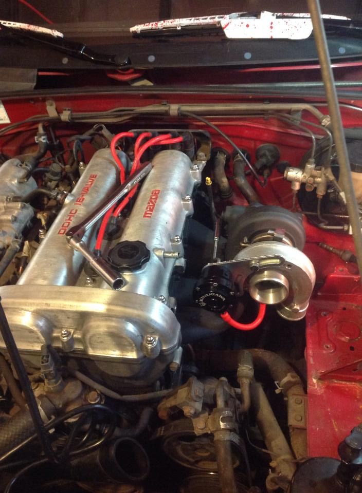
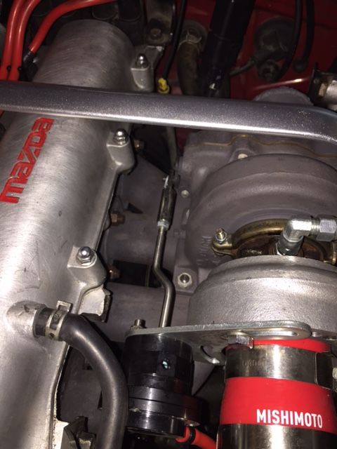
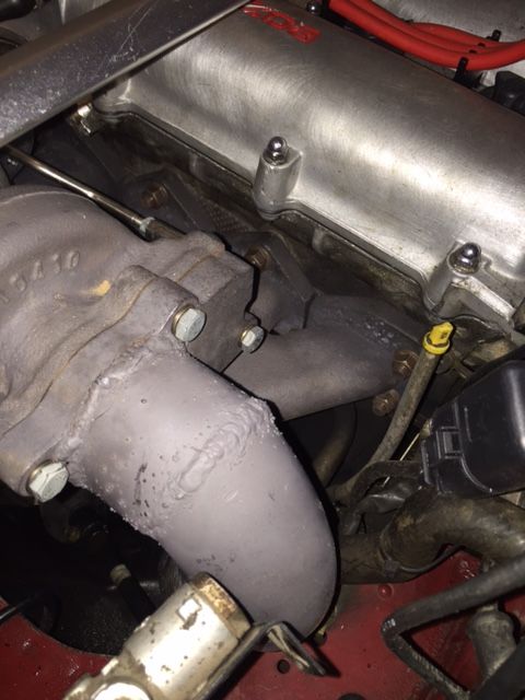
Here are some close up shots of my hot parts installed.
I will be upgrading to inconel studs and proper hardware for my hot parts soon.
I continued my last bit of installation with my intercooler piping. Again, solid and tight connections here are key to a successful install. Take your time, be methodical, and triple check all of your couplers and clamps when you're finished.
A look at the front end with the hood closed for the first time in months. Thank goodness it clears my massive turbo
Since I was finally finished with crawling up underneath the car to bolt/unbolt the exhaust and meticulously checking for clearance issues with my intercooler piping and exhaust, I decided to relieve the jack stands for a while and lower the car back down again.
I got a special buy on a lowered jack from Harbor Freight for $69 with a buddy one weekend which has been a great tool investment so far- It also has a one year warranty one it which I can renew every year.
My front lip sits about the 3.5" from the ground for reference of how low the jack is.
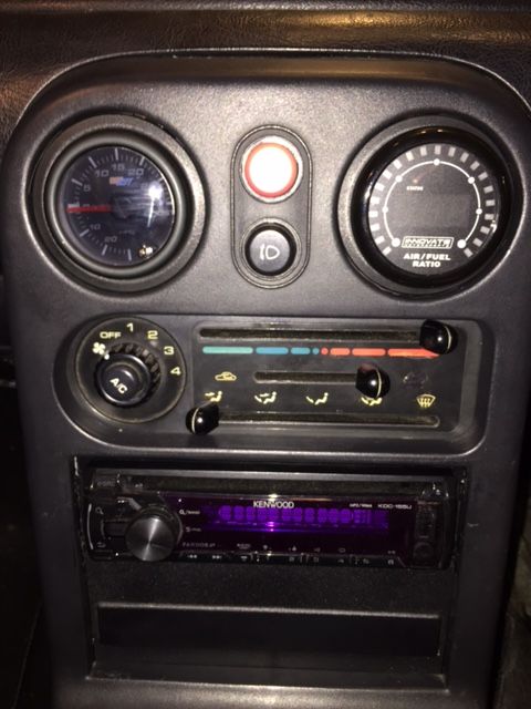
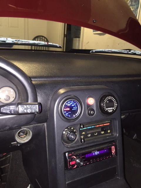
Next up was to get Innovative (Haha) with some gauge installs. I don't like the look of pillar pod setups very much and I didn't really want to hack up my space-delete plate that sits underneath my radio so I decided to use the two middle OEM air vent holes to mount my gauges.
After coming up short while searching for a good write up on exactly how to do this, I just went for it. Sometimes you just have to go for things!
I removed the two vents from their holes and took off their plastic retaining rings because you need them to allow the gauges to sit flush in the holes.
I wrapped the body of my gauges with 1-2 layers of electrical tapes to ensure that the plastic retaining rings fit snugly around them. After test fitting the gauges with the tombstone cover on, I thought about routing options as far as wires and the pressure reference line goes.
I ultimately decided to install the boost gauge on the left and air-fuel ratio gauge on the right. I did this because my AFR gauge is wired directly to the my ECU and I wanted to have those wires as short as possible. We're talking about a difference of less than six inches of wire, though, so I don't really know why I reasoned it that way.
Here is how they turned out. They almost look like they belong there!
I drilled a few holes here and there in the air ducting in order to route my wires and reference line. That worked very well for me.
Boost gauge
Air-Fuel Ratio gauge
Note: It is kind of hard to read all of the boost gauge because the shroud from the tombstone ever so slightly covers up a bit of the gauge face. This can be remedied with a bit of neck stretching!
You can see how I have a bit of a "blind spot" from the 5 vacuum to 5 boost readings
Wiring up the AFR gauge:
The Innovate MTX-L has five wires and are as follows:
Red- Switched 12V source
Black- Ground- Use a signal ground instead of a conventional ground for less electrical noise. The DIYPNP has multiple SG pins.
White- Headlight dimmer switch- Ground this if you don't plan on using it.
Yellow- Analog wire (0V-5V)- Use this if you are installing a wideband O2 sensor.
Brown- Analog wire (0.1V-1V)- Use this if you are wiring it to your stock narrowband O2 sensor.
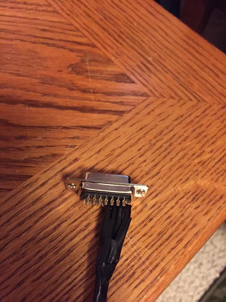
Note: You want to wire all of your wires from the AFR gauge into the same place in attempt to decrease the amount of electrical "noise" and ease any trouble-shooting processes you might have to go through. I chose to wire my AFR gauge directly to my DIYPNP. There is a convenient DB-15 connector that makes doing this very easy.
Wiring my AFR gauge up to my DIYPNP:
1. Jump the appropriate pins on the main board itself.
2. Make a wiring loom with 4 wires and make the respective connections into the DB-15 connector adapter
3. Connect the appropriate wires to the extension loom from AFR gauge itself.
I wired my DB-15 pins accordingly:
1 to 12V
2 to SG- I spliced into my 4C wire because both of the SG pins on that side of the board were already populated
3 to nowhere- Was going to utilize the headlight dimmer switch but then decided against it
4 to 4N- My 4N on the main board jumps to 4N on the connector board which jumps to 02 on the main board
I even insulated my wires in a 4-2-1 configuration- For maximum airflow, of course!
I wired my DB-15 connector pins accordingly: (These go to the AFR gauge itself with the help of my extension loom)
1- Red
2- Black
3- Orange (Connects to white wire from AFR gauge. I just didn't have white wire at the time).
4- Yellow
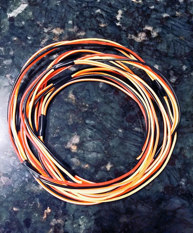
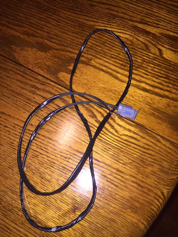
My extension loom that I made from an old radio wiring harness. I gave the loom some proper insulation after everything was installed and tested.
Wiring up the boost gauge:
This was very simple and took me almost no time at all. The Glowshift boost gauge has four wires and are as follows:
Red- Switched 12V source
Yellow- Constant 12V source- This is used so the gauge can remember which color you had it last set to
Orange- Headlight dimmer switch- Ground this if you don't plan on using it.
Black- Ground- A conventional ground will work just fine for this application.
I just tapped into the appropriate wires from my radio wiring harness while wiring up my gauge. Most people will say to avoid running multiple things off of your radio wires because it is good practice to have things like this in isolated circuits. All of that being said, I installed mine like this and have not had any issues thus far.
Continuing on my wiring high, I decided to finally install my intake air temperature sensor. I used the GM-Style IAT kit with steel bung from Diyautotune.com.
Here is my connector loom. I gave it some proper insulation after it was installed and tested.
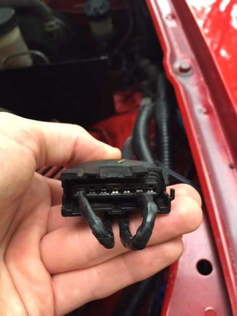
Wiring it up is extremely straightforward as it's just two wires. Connect the two wires from the IAT sesnor to pins 1 and 6 of the factory air flow meter connector. These pins are not polarity-specific so it doesn't matter which wire you connect to which pin.
I routed my heat-shielded IAT sensor wires along the top of my radiator.
My installed IAT sensor wires. Zip tie these down to the factory AFM connector loom to keep things tidy.
Now that all of my wiring with finished, I decided to tidy things up a bit and run any wires and reference lines through the firewall. I had the O2 sensor wiring, boost gauge reference line, and MAP reference line to worry about. I only ended up having to drill one hole in the firewall because I found two other unused ports I could use.
Use grommets when running anything through the firewall to protect from chafing. Spend the few extra bucks; It's worth it.
The O2 sensor wiring.
The boost gauge and MAP reference lines. Iirc, I had to drill the hole on the right.
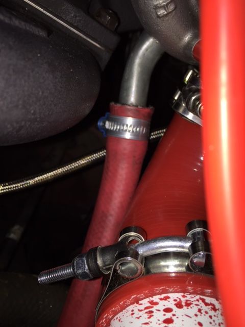
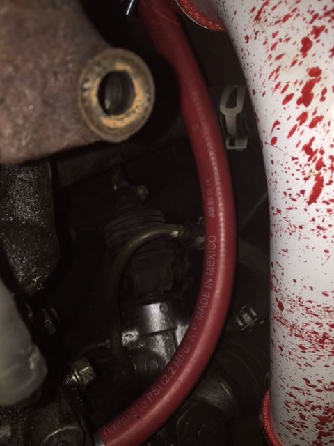
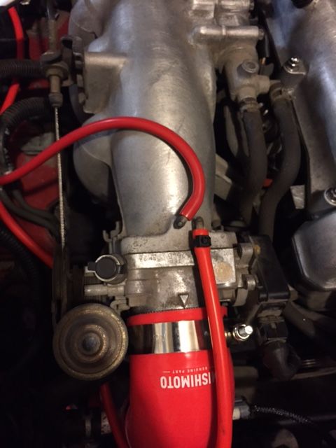
I guess this is a fine enough time as any to discuss reference lines on the left side of the engine. I am no expert in these and there very well could be better locations to get these references at, but these have worked great for me so far.
I used the top nipple facing the inside of the car on the intake manifold for my MAP reference line- This line goes directly to the on-board MAP sensor installed on the ECU.
I used 4mm ID hose for the MAP sensor and 3mm ID hose for the boost gauge and BOV. Notice how both of these lines are POST- throttle body.
I used the bottom nipple facing the front of the car for my boost gauge and blow off valve reference lines- These lines go to the boost gauge and the BOV.
If you have a BOV like mine that has two nipples on it, use the top one like this. It is the bigger of the two. I can't explain this yet but I know it works!
I had one more mechanical adventure ahead of me and that was to address fueling and ignition.
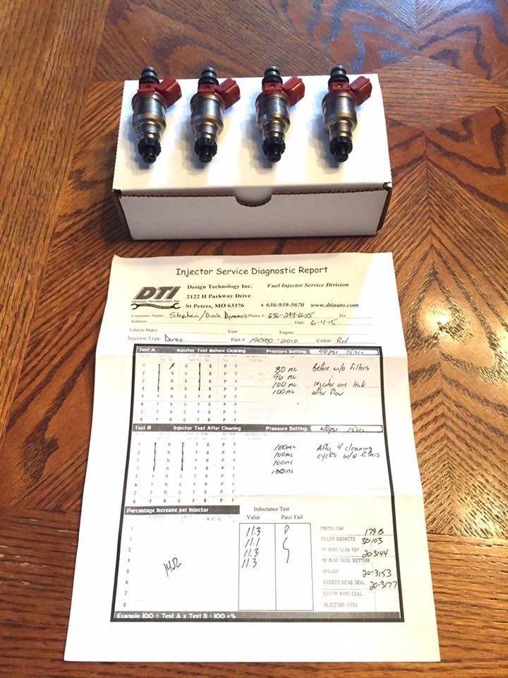
I got the RX-7 460cc Red Tops because I was able to pick up a set of them for $50. I will eventually be upgrading to an injector with a better flow pattern, though.
I did spend $100 on getting them professionally cleaned and flow tested for the time being, just for good measure. This price also included all new seals, gaskets, pintle caps, and pintle baskets.
I'd definitely recommend getting any set of injectors flow-tested unless if you know for sure that their flow rates match each other and are good to go. Even brand new injectors can benefit from this to ensure that they have matching flow rates.
I went with NGK BKR7E (4644) plugs because that seemed to be the consensus online. Mine are currently gapped to 0.034" but I will be decreasing the gap down to 0.030" soon.
At this point in the build, I almost reached a point of sadness. I was going to miss working on this whole build. The thought of feeling boost for the first time excited me enough to push through, though!
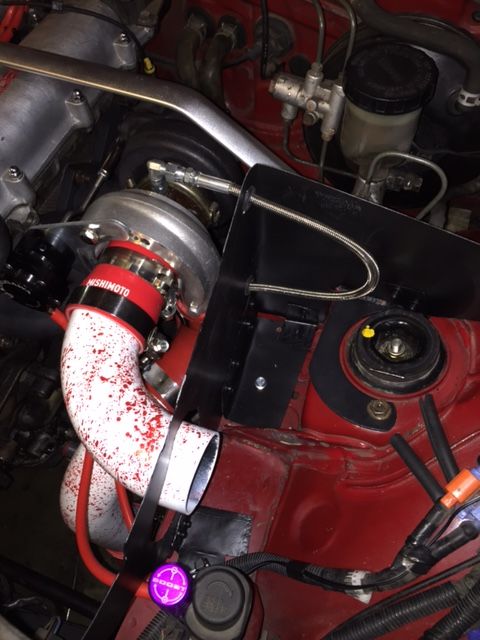
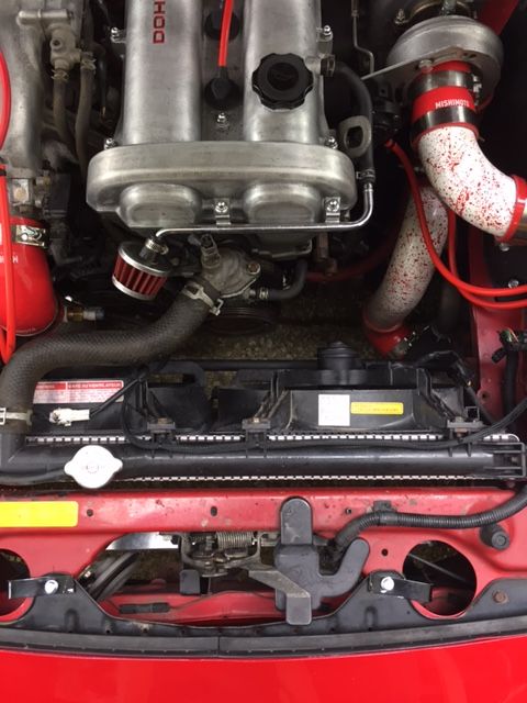
Shot of the engine bay with everything installed.
I filled the car back up with oil and installed a new filter. I used Castrol GTX 5W-30 for the first couple hundred miles. I put the interior of the car back together. I loaded the DIYPNP with the appropriate base map and started the car. Oh, and I forgot to pull the 10A ST SIG fuse.
Again, I forgot to pull the 10A ST SIG fuse.
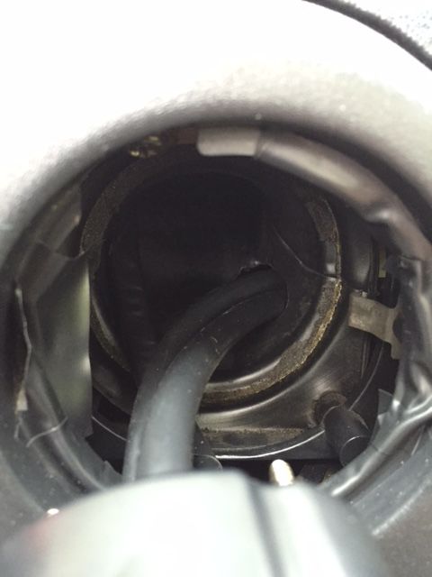
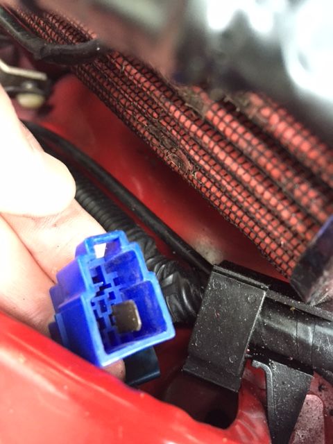
Needless to say, I blew the TIP125 power transistor on the board of my ECU. I ended up just jumping the F/P and GND pins in the engine diagnostics box for the time being so that the fuel pump will always be on when the car is on. I am waiting on a replacement transistor now.
Here is my temporary workaround to remedy my mistake.
After that whole ordeal, I gave the car another go at starting up- Success!
Next was to verify the base timing that I had set a few months back. After getting that set, I was (almost) ready for my first drive!
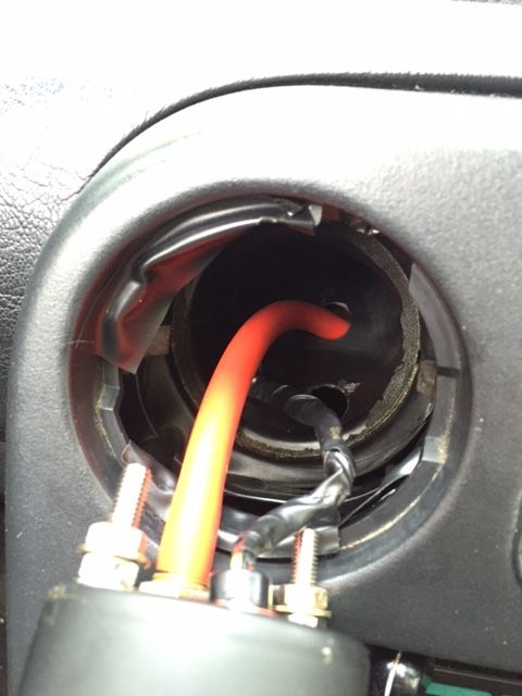
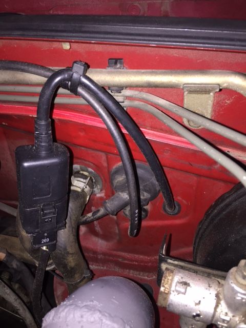
Here is a convenient power source for your timing light when verifying the timing. This connector is right by your diagnostics box.
Luckily, I was able to find a guy with a very similar setup as mine to supply me with a modified base map that he had been working on for a while now. I changed my fuel injector size and configured my wideband settings and hoped for the best. Everything seemed to be functioning properly and more importantly, safely.
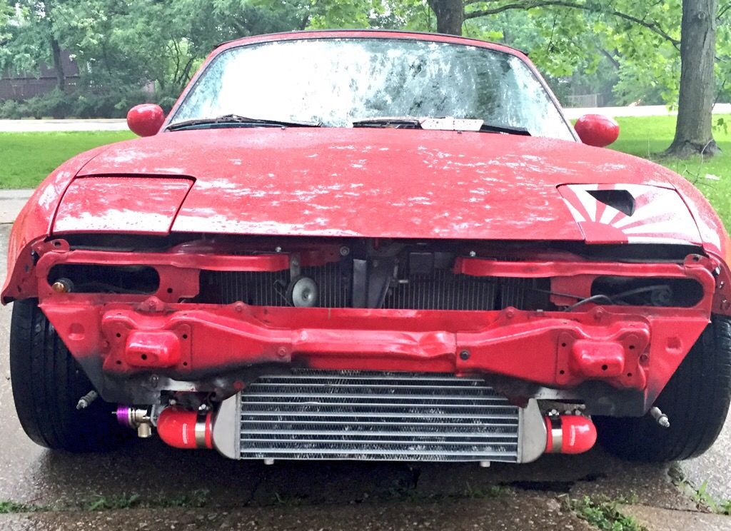
Here she is after the first test drive! I didn't want to install the bumper cover yet just in case I came across any boost leak issues...
Let me be the first to tell you; there isn't anything more disheartening than realizing that your boosted car won't boost on it's first test drive.
After some troubleshooting, it turns out I had a combination of a loose wastegate arm to flapper door connection and an exhaust leak where the exhaust housing mates the manifold. After addressing these issues, it was time for another test drive.
Success! Let me be there first to tell you; there isn't anything more amazing than realizing that your five months of research, hard work, and late nights finally paid off. My boosted car boosted.
One of my car guy buds snagged this shot of me with the car. I had to keep the bumper off for a little while to feel like a typical 240 owner.
My girlfriend snagged this shot of me without me noticing while I was trying to gain some traction on the wet roads.
A rolling pic of some friends and I heading out to a big car meet.
Classic engine bay shot at aforementioned car meet- Turned out pretty nicely!
This concludes the first three posts of my DIY turbo build thread. I will be continuing to update this as I fit the car with supporting modifications and experiment more with tuning. Some future mods that I will be (hoping) to get to before August are a new clutch setup, new brake setup, a SCCA- Certified roll bar, wiring for sequential fuel injection, variable TPS retrofit, and possibly Toyota COPs.
I learned a lot during this build process and I still have a lot more to learn but I could not be happier with how far I have come. The friends that I have met and the new connections I have made along the way have really made this an amazing experience for me.
More coming soon!
Last edited by typicalsteve; Jun 29, 2015 at 07:02 PM.
<p>Still shouldn't have used Rx-7 injectors. Thats just 150 down the drain that could have gone towards better injectors.</p><p>Other than that nice build. Stock clutch should start slipping soon if you drive hard enough </p>
1. Your intercooler pipes need beads. Like the ones on the IC.
2. That grommet in your intake box next to your turbine housing is going to melt and your oil supply line will either wear through the intake box sheet metal (medium bad) or vice-versa (full bad).
3. High temp paint? On a turbo exhaust manifold and turbine? Really? Doesn't matter though, it'll burn off on its own.
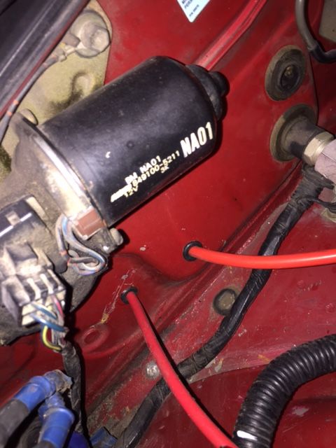
4. Need to protect your brake master. Heat shield is preferred, but a lot of people just run reflective tape around it.
5. If you had posted while you were building, we could have helped you more.
6. You've got a cute brother-in-law and SCOTUS now says you guys can marry and drive in your Miata together -- better break it easy to your sis.
Last edited by hornetball; Jun 29, 2015 at 07:56 PM.
<p>Still shouldn't have used Rx-7 injectors. Thats just 150 down the drain that could have gone towards better injectors.</p><p>Other than that nice build. Stock clutch should start slipping soon if you drive hard enough </p>
Yeah, I know... I realized that after everything was said and done. Like I said, I will be upgrading injectors as soon as I finally decide on which ones to go with.
The clutch is indeed slipping under boost. I should have addressed that before or during the build. But I just picked up a Mazdaspeed flywheel today for $25 shipped! I will be ordering the ACT HD clutch kit this week and will hopefully have it installed by next weekend!
1. Your intercooler pipes need beads. Like the ones on the IC.
2. That grommet in your intake box next to your turbine housing is going to melt and your oil supply line will either wear through the intake box sheet metal (medium bad) or vice-versa (full bad).
3. High temp paint? On a turbo exhaust manifold and turbine? Really?
4. Need to protect your brake master. Heat shield is preferred, but a lot of people just run reflective tape around it.
5. If you had posted while you were building, we could have helped you more.
6. You've got a cute brother-in-law and SCOTUS now says you guys can marry and drive in your Miata together -- better break it easy to your sis.
Thanks for the feedback, man!
1. I know. I am going to bug my welder friends soon about tigging up some of my pipes for me.
2. I made the hole in the intake box a bit larger so the oil line isn't really pressured against the inside of the grommet. I will keep close watch on it, though!
3. The paint is good to 2,400 degrees Fahrenheit. I think (hope) it will hold up.
4. I am working on heat shielding at the moment. I will be installing a license plate over the exhaust housing/dp soon. I haven't decided on making up a heat shield for the brake master or just wrapping it. I will probably just wrap it.
5. Well, I'm here now!
6. Ah, as nice as that sounds, I've got a thriving hair salon business to maintain and can't have any other passengers at this time. Too many hairdryers that need to fit.
Last edited by typicalsteve; Jun 30, 2015 at 03:40 AM.
Yeah, I know... I realized that after everything was said and done. Like I said, I will be upgrading injectors as soon as I finally decide on which ones to go with.
The clutch is indeed slipping under boost. I should have addressed that before or during the build. But I just picked up a Mazdaspeed flywheel today for $25 shipped! I will be ordering the ACT HD clutch kit this week and will hopefully have it installed by next weekend!
You want the flow force injectors from TSE. Spend the $300 and be done with it. I have used almost every other type of injector on the market, and short of going with ID's they are the best you can get at a good price.
Order the FM1 clutch instead of ACT HD. It is slightly cheaper and holds more torque. Clutch pedal is also bit easier on the leg.
I'll look into those injectors, thanks! How are they better from the others?
I was thinking about the FM1 kit but I don't want a lightweight flywheel. I want to keep a stock one in order to maintain low end torque. I've heard great things about both, though. Maybe I'll call up FM and see if they'll sell me a kit whithout the lightweight flywheel.
I said get the FM1 clutch not the full happy meal.
The flow force injectors are better because they are the new EV14 design. You can search on here for the mustang gt500 injectors to find out more information about them.
Entertaining read.
fm1>act all day urry day
ev14>ev1 all day urry day
the paint on the mani wont hold up. but it will likely turn a nice white color after it burns off in a bit, matching your ic piping
Originally Posted by concealer404
Light flywheel actually would improve low end torque in lower gears. At least to the wheels. Won't actually make or remove power.
1. removing the a/c and p/s just makes the car hard to daily--not worth the weight savings if it's not a dedicated track car.
2. next time go 3" exhaust or bust.
3. your IC is trashed. all the fins are bent and the core is beat the **** up. replace it with a decent core.
4. would bang (the guy, not the girls).
5. for other noobs reading this:
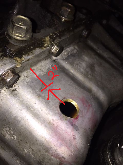
Put the oil drain port as high up as possible. This makes sure the oil dumps in above the oil level and doesn't cause slow darin issues.
6. Next time use smaller gauge wire in the case, like 18g tops. that's really thick wire you used to build the DIYPNP.
7. Put fuel pump to 4O and then jump the two pins in the AFM connector to allow the MS to run the fuel pump. This is better than the high-side driver.
8. very much dislike the innovate controller in the engine bay. It WILL eventually die prematurely. You should have wired it up inside the cabin and ran the o2 sensor under the shift boot. So much less work and runnign wires into the engine bay, you could have ran power/grounds directly to the DIYPNP and had it sit under the radio.
9. The MAP reference you used for the MS on the TB is a HORRIBLE location, you're going to have all sorts of MAPdot issues. It's really best to tee off the FPR, and in the least you'll want to add an inline fuel filter to clean up the signal.
10. Use the dual ports of the BOV as intended. You should already have a boost source pre-tb post-IC anyway for your turbo source...if you don't then you should add it and do it right.
11. your driving style makes you look like a little girl... who grabs the right side of the wheel with your left hand like that? and in wet driving none-the-less. Do you want to replace body panels now after all this work?
12. rising sun is offensive and should be outlawed.
I said get the FM1 clutch not the full happy meal.
The flow force injectors are better because they are the new EV14 design. You can search on here for the mustang gt500 injectors to find out more information about them.
Ah, I see. I like that price a lot better. I have heard good reviews from both the ACT and FM setups. The FM price is a lot better, though.
I've looked into that design before. I will plan on upgrading those after I address some other issues first. Thanks again
1. removing the a/c and p/s just makes the car hard to daily--not worth the weight savings if it's not a dedicated track car.
2. next time go 3" exhaust or bust.
3. your IC is trashed. all the fins are bent and the core is beat the **** up. replace it with a decent core.
4. would bang (the guy, not the girls).
5. for other noobs reading this:
Put the oil drain port as high up as possible. This makes sure the oil dumps in above the oil level and doesn't cause slow darin issues.
6. Next time use smaller gauge wire in the case, like 18g tops. that's really thick wire you used to build the DIYPNP.
7. Put fuel pump to 4O and then jump the two pins in the AFM connector to allow the MS to run the fuel pump. This is better than the high-side driver.
8. very much dislike the innovate controller in the engine bay. It WILL eventually die prematurely. You should have wired it up inside the cabin and ran the o2 sensor under the shift boot. So much less work and runnign wires into the engine bay, you could have ran power/grounds directly to the DIYPNP and had it sit under the radio.
9. The MAP reference you used for the MS on the TB is a HORRIBLE location, you're going to have all sorts of MAPdot issues. It's really best to tee off the FPR, and in the least you'll want to add an inline fuel filter to clean up the signal.
10. Use the dual ports of the BOV as intended. You should already have a boost source pre-tb post-IC anyway for your turbo source...if you don't then you should add it and do it right.
11. your driving style makes you look like a little girl... who grabs the right side of the wheel with your left hand like that? and in wet driving none-the-less. Do you want to replace body panels now after all this work?
12. rising sun is offensive and should be outlawed.
Thanks for the input, Brain.
1. This car isn't a daily by any means. Working towards making it a track car.
2. Noted.
3. I've been looking into the Fab9 IC
4. Who wouldn't?
5. Mine is 2.2 inches down from the oil pan flange...
6. Noted.
7. Schematically, it's the same. Yeah?
8. Noted. Will address this during my next hot side tear down.
9. Haven't heard anything about this but will look into it..
10. As stated in the thread, will be addressing that when it becomes as issue
11. I'm not a girl. Just for clarification. I don't think, at least.


 I have only recently found some success with this.

 I even tested the waters with welding myself! I ended up having my buddy go back over the hangar weld because I didn't trust my weld to hold up... Again, maybe some day
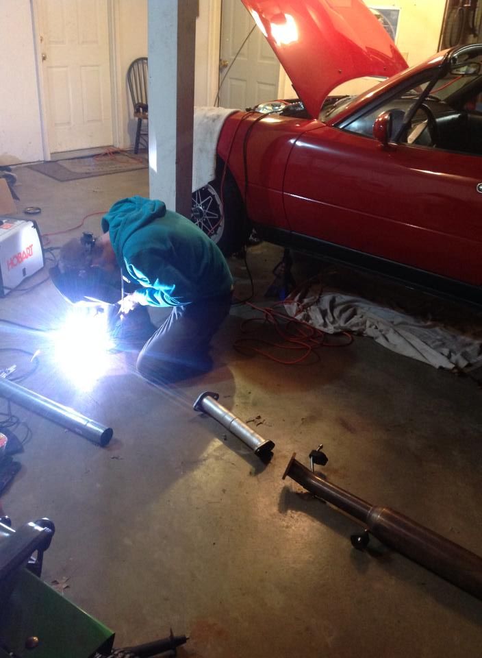
 Repeat the process until nothing but clear liquid is coming out.
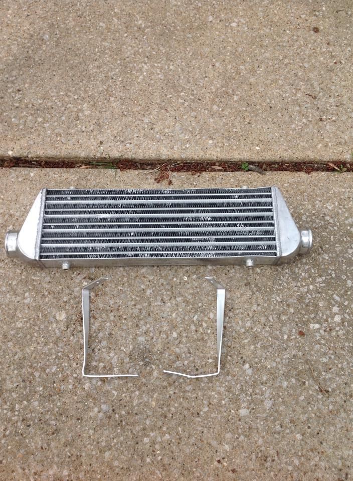


 1
1


 Let me be there first to tell you; there isn't anything more amazing than realizing that your five months of research, hard work, and late nights finally paid off. My boosted car boosted.