DJWade's (Hopefully) California Legal LFXocet Swap Build
 07-16-2017, 12:49 AM
#81
Junior Member
Thread Starter

Join Date: Sep 2016
Location: Concord, CA
Posts: 122
Total Cats: 12
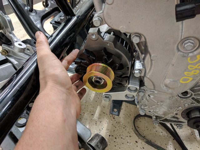
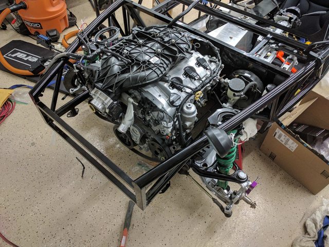
The spacers from V8 Roadsters arrived along with the power steering retrofit kit, so I've jumped into working on things this weekend as much as I've been able to manage. My excitement got the better of me, and I couldn't help but test fit the engine into the car now that I had the spacers. The big thing I was trying to figure out was if I could modify the OEM alternator to fit with the interference at the engine bay frame rails. Long story short, there's no easy way to modify the alternator or the bracket to make things fit.
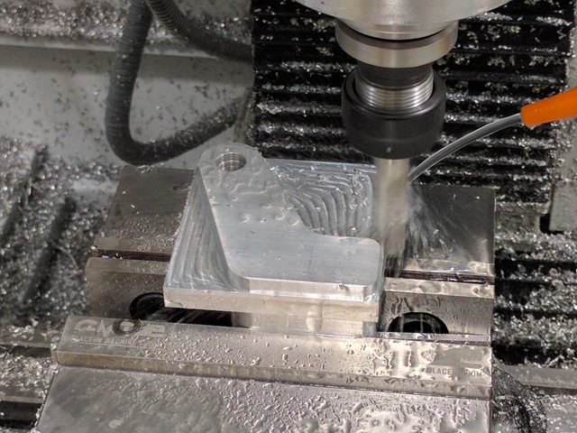
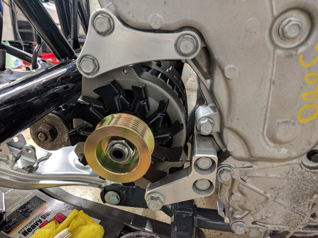
Fortunately, I already had the one wire alternator anticipating that the OEM wouldn't work. I felt rather motivated today, so I grabbed some measurements comparing the two alternators, then working off the available mounting holes on the engine, modeled and machined the main portion of the bracket. it's not the prettiest thing in the world, and I still want to add some additional support besides at the top to hold it in place, but I'm really happy with the fitment at the very least, and going from no bracket to a custom machined bracket in 3 hours felt pretty good.

Tomorrow morning I'll make a small bracket to hold the second mount location on the alternator up and away from the frame rail using the two bolts just above it on the front of the engine.
I already have the back half of the lower bracket designed and the .NC made, it's just waiting on me squaring up some stock and pushing "start". Tomorrow I'll probably pull the engine back out now that I've confirmed the new alternator will fit, and start preparing the transmission to mate back up with the engine. It's finally starting to feel like there's no major roadblocks to major progress now besides my time, which is the best one to have.
Fortunately, I already had the one wire alternator anticipating that the OEM wouldn't work. I felt rather motivated today, so I grabbed some measurements comparing the two alternators, then working off the available mounting holes on the engine, modeled and machined the main portion of the bracket. it's not the prettiest thing in the world, and I still want to add some additional support besides at the top to hold it in place, but I'm really happy with the fitment at the very least, and going from no bracket to a custom machined bracket in 3 hours felt pretty good.
Tomorrow morning I'll make a small bracket to hold the second mount location on the alternator up and away from the frame rail using the two bolts just above it on the front of the engine.
I already have the back half of the lower bracket designed and the .NC made, it's just waiting on me squaring up some stock and pushing "start". Tomorrow I'll probably pull the engine back out now that I've confirmed the new alternator will fit, and start preparing the transmission to mate back up with the engine. It's finally starting to feel like there's no major roadblocks to major progress now besides my time, which is the best one to have.

Reply
 0
0

0
 07-16-2017, 10:41 AM
#83
Junior Member
Thread Starter
Join Date: Sep 2016
Location: Concord, CA
Posts: 122
Total Cats: 12
I had been considering looking for those mounts that move the alternator to the upper drivers side, but from what I've been able to tell, all of the applications that move the alternator, swap the PS pump to the alternator's original location, and I wasn't sure if the PS pump's pulley would create an interference in the same location, or if the alternator would prevent the use of the camaro's oil filter, like you mentioned. I'm a big fan of the accessibility of that oil filter, so I didn't want to risk losing it. The other factor was that it was simply easier and cheaper for me to design and machine a new custom bracket than try and do all the legwork to swap the alternator and PS pump for an unknown end result.
Reply
0
0
07-16-2017, 12:36 PM
#84
There are no brackets needed the alternator just bolts directly to the block/front cover. Iirc the ps pump is the same way. I think the ps pump pulley is smaller than the alternator but not definite about that. If you want dimensions or any gm info I work on these **** heaps wonderful feats of engineering every day. Understandable I'm just throwing it out there in case you didn't know.
Reply
0
0
07-16-2017, 02:36 PM
#85
Junior Member
Thread Starter
Join Date: Sep 2016
Location: Concord, CA
Posts: 122
Total Cats: 12
There are no brackets needed the alternator just bolts directly to the block/front cover. Iirc the ps pump is the same way. I think the ps pump pulley is smaller than the alternator but not definite about that. If you want dimensions or any gm info I work on these **** heaps wonderful feats of engineering every day. Understandable I'm just throwing it out there in case you didn't know.
Oh, interesting! I had looked at it quickly thinking that was the case, but I must have missed the mounting points on the drivers side. I'll give that a look again when I get back from machining the last pieces today.
Given that you work on these, any issues to keep an eye out for engine wise? I heard there were some timing chain issues early on, but got fixed with the later model years (I'm using a 2015 engine).
Reply
0
0
07-16-2017, 06:45 PM
#86

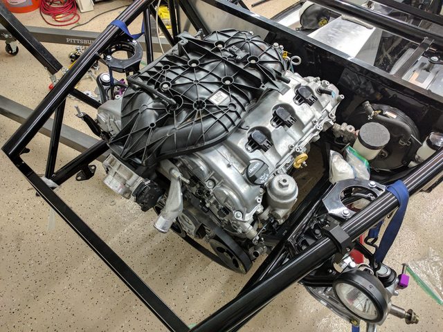
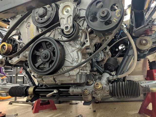
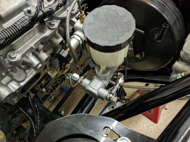
See the bolt that is holding the filter housing to the block? That hole and one to the left of it on the front cover are the upper mounting points for a fwd alternator. The lower mounting hole is down somewhere by the belt tensioner.
I haven't really seen that many issues after 13ish so probably just carbon build up and leaking evap purge solenoids. Pre 13ish had issues with chains, leaking front covers, and I've seen a few dropped valves but almost all of those have been in impalas.
Reply
0
0
07-16-2017, 08:18 PM
#87
Junior Member
Thread Starter
Join Date: Sep 2016
Location: Concord, CA
Posts: 122
Total Cats: 12
See the bolt that is holding the filter housing to the block? That hole and one to the left of it on the front cover are the upper mounting points for a fwd alternator. The lower mounting hole is down somewhere by the belt tensioner.
I haven't really seen that many issues after 13ish so probably just carbon build up and leaking evap purge solenoids. Pre 13ish had issues with chains, leaking front covers, and I've seen a few dropped valves but almost all of those have been in impalas.
I haven't really seen that many issues after 13ish so probably just carbon build up and leaking evap purge solenoids. Pre 13ish had issues with chains, leaking front covers, and I've seen a few dropped valves but almost all of those have been in impalas.
Speaking of which, I made my way back to the office this morning to finish up the last two pieces of the bracket. Only took a few hours, and they turned out pretty well. The only issue that came up later is that I wasn't aggressive enough with the radius between the top two holes, and had to manually shave some off with a grinding wheel once I was back in my garage. Ruins the aesthetics if you look closely enough, but overall I'm still really happy with how things turned out.
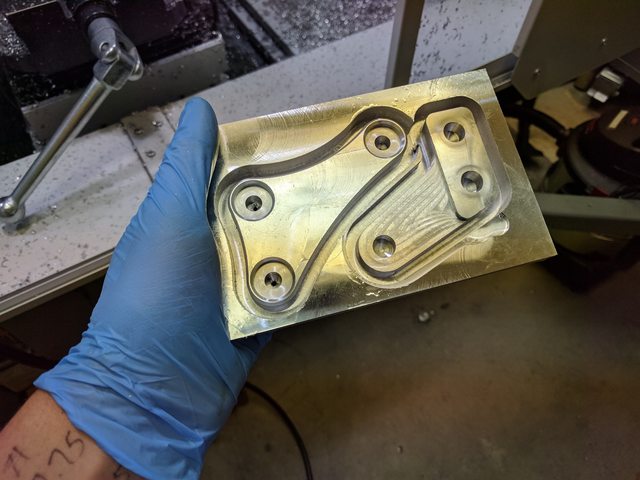
I only have two of the three mounts on right now (the last one goes in the same location as the lower, but behind to add more torsional rigidity), but it's already really firmly mounted in place. I'm really happy with how it all turned out.
Reply
0
0
07-22-2017, 03:18 AM
#88
Junior Member
Thread Starter
Join Date: Sep 2016
Location: Concord, CA
Posts: 122
Total Cats: 12
The weekend has arrived, and with it, some more progress.
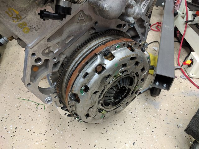
After having test fit the block, I finally got around making the last little adjustments I needed to in order to finally get the engine in the chassis for good (hopefully). Once I had pulled the engine back out, I got to work re-attaching the flywheel and clutch. The flywheel had a fair amount of surface rust on the outside, but the surface looked brand new, as it should for only having 500 miles or so. A quick clean with acetone and non-shedding wipes, and the clutch was back in place.
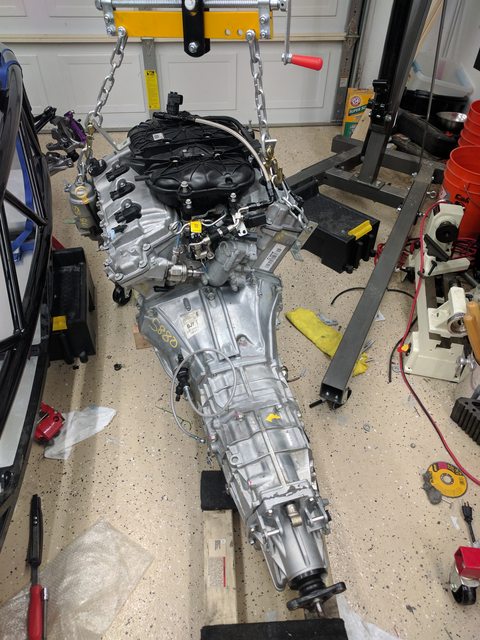
With a bit of wrestling to get it into position, I got the transmission and starter mounted back together with the engine and got everything torqued and loctite'd together back to spec.
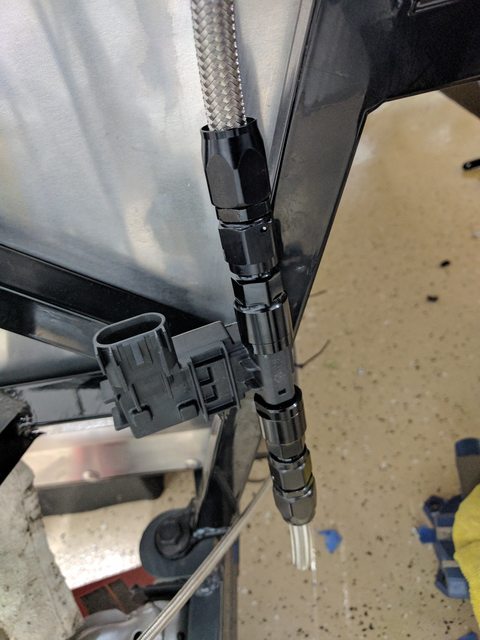
Before I installed the engine and transmission, I had to modify the -6AN line that comes with the LFX fuel kit from V8 roadsters to accept the FlexFuel sensor, so I took care of that while I had the chance. I probably could have done it later, but being able to saw a hose without the engine in the bay saved a lot of headache in the future.
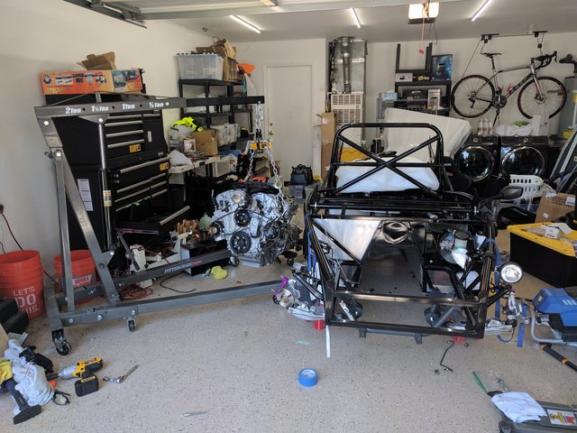
With that taken care of, there wasn't really anything left to do other than get the engine into its new home. Even with just myself, this was pretty easy. Not having body panels in the way of anything makes nearly everything easier.
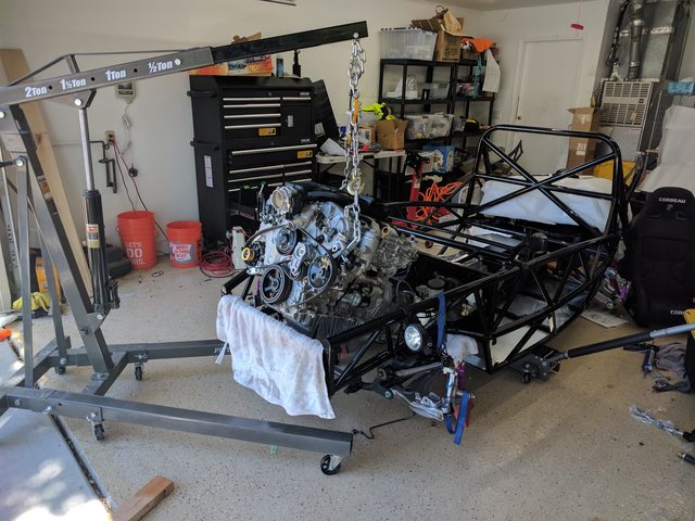
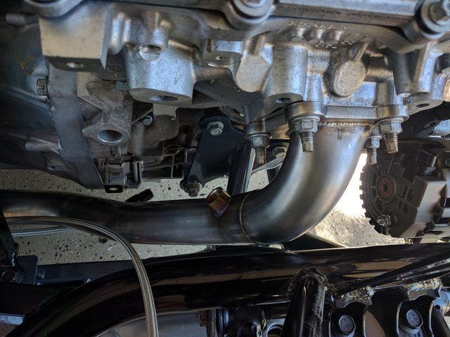
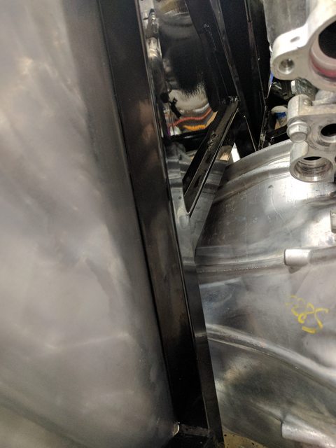
Once it was bolted to the engine mounts, I installed the passenger downpipe to check for any interference. It's pretty tricky to get it on with the studs in place for the exhaust, so i may look into some shorter studs to make it a little easier for the exhaust shop when they're fabbing the exhaust in a month or two. Overall clearances look pretty good. The clearance between the top of the transmission and the chassis tunnel is close, but I think that will open up more once I install the transmission support and get the output flange to the right angle to match the rear differential 1.5� pinion angle.
After having test fit the block, I finally got around making the last little adjustments I needed to in order to finally get the engine in the chassis for good (hopefully). Once I had pulled the engine back out, I got to work re-attaching the flywheel and clutch. The flywheel had a fair amount of surface rust on the outside, but the surface looked brand new, as it should for only having 500 miles or so. A quick clean with acetone and non-shedding wipes, and the clutch was back in place.
With a bit of wrestling to get it into position, I got the transmission and starter mounted back together with the engine and got everything torqued and loctite'd together back to spec.
Before I installed the engine and transmission, I had to modify the -6AN line that comes with the LFX fuel kit from V8 roadsters to accept the FlexFuel sensor, so I took care of that while I had the chance. I probably could have done it later, but being able to saw a hose without the engine in the bay saved a lot of headache in the future.
With that taken care of, there wasn't really anything left to do other than get the engine into its new home. Even with just myself, this was pretty easy. Not having body panels in the way of anything makes nearly everything easier.
Once it was bolted to the engine mounts, I installed the passenger downpipe to check for any interference. It's pretty tricky to get it on with the studs in place for the exhaust, so i may look into some shorter studs to make it a little easier for the exhaust shop when they're fabbing the exhaust in a month or two. Overall clearances look pretty good. The clearance between the top of the transmission and the chassis tunnel is close, but I think that will open up more once I install the transmission support and get the output flange to the right angle to match the rear differential 1.5� pinion angle.
Reply
0
0
07-26-2017, 11:24 PM
#89
Junior Member
Thread Starter
Join Date: Sep 2016
Location: Concord, CA
Posts: 122
Total Cats: 12
Update time! Lots of progress made, not all of it easy to see.
The first major step forward was with engine wiring. The modified harness from V8 Roadsters arrived, and I quickly got around to putting it on. Basically everything just fit right into place, which alleviated a ton of the concerns about not documenting the wiring enough. I'm still in the planning phases for the chassis wiring harness, but there's not much more to do before starting to make a template.
I also got the power steering rack hard lines swapped over for the AN fittings and braided lines, then mounted into place. It's a bit of a tight squeeze, but I don't think I'll have any issues with it. I also purchased a power steering cooler, which I need to sort the mounting for, as well as the remaining lines, but I still need to sort the reservoir before I can finish it up completely. With the rack now in place, I was able to install the steering column. I got some upgraded hardware to swap out the aluminum button head screws with stainless, but in the process of switching them out, stripped 4 of the 10 heads. Drilling them out was a major paint, so learn from my mistakes: If you're installing an NRG hub and quick release, just throw away the included hardware, and save yourself some headache if you ever need to take it off for any reason.
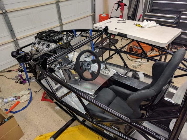
I was also able to start fitting in the coilover spacers and front coilovers. The front end is finally starting to resemble a functional suspension. I had swapped the spacers front/back which had caused a minor panic attack when the studs from the coilovers interfered with the bolts mounting the spacers to the chassis, but swapping them into the right position solved that. No need to change suspension... at least not yet. I suspect I'm going to be fairly oversprung for my intended driving, and every attempt to source Tein springs with the right spring rates has fallen through. I need to grab the measurements and see if there's an affordable non-Tein replacement spring option that will get me into the right range.
Finally, I've started the process of mounting the transmission support to the chassis. A few rivets for the floor pan had to be drilled out, and it's a bit of a tight squeeze, but I should be able to get it bolted into place without too much trouble after picking up a bunch of 10.9 grade bolts tomorrow.
While I'm waiting for the new 949racing 6UL wheels to come out, I finally bit the bullet and ordered tires for my cheapo rims. I was debating getting something cheap because I can only assume I'm going to be going through tires fairly quick as I get used to 300+ HP on an exocet, but in the end just decided to get some 225/45r15 RS4s. They should be here on friday and mounted this weekend. With the tires mounted, I'll be looking at installing the rest of the driveline so I can finally send it for some exhaust work as a roller.
The first major step forward was with engine wiring. The modified harness from V8 Roadsters arrived, and I quickly got around to putting it on. Basically everything just fit right into place, which alleviated a ton of the concerns about not documenting the wiring enough. I'm still in the planning phases for the chassis wiring harness, but there's not much more to do before starting to make a template.
I also got the power steering rack hard lines swapped over for the AN fittings and braided lines, then mounted into place. It's a bit of a tight squeeze, but I don't think I'll have any issues with it. I also purchased a power steering cooler, which I need to sort the mounting for, as well as the remaining lines, but I still need to sort the reservoir before I can finish it up completely. With the rack now in place, I was able to install the steering column. I got some upgraded hardware to swap out the aluminum button head screws with stainless, but in the process of switching them out, stripped 4 of the 10 heads. Drilling them out was a major paint, so learn from my mistakes: If you're installing an NRG hub and quick release, just throw away the included hardware, and save yourself some headache if you ever need to take it off for any reason.
I was also able to start fitting in the coilover spacers and front coilovers. The front end is finally starting to resemble a functional suspension. I had swapped the spacers front/back which had caused a minor panic attack when the studs from the coilovers interfered with the bolts mounting the spacers to the chassis, but swapping them into the right position solved that. No need to change suspension... at least not yet. I suspect I'm going to be fairly oversprung for my intended driving, and every attempt to source Tein springs with the right spring rates has fallen through. I need to grab the measurements and see if there's an affordable non-Tein replacement spring option that will get me into the right range.
Finally, I've started the process of mounting the transmission support to the chassis. A few rivets for the floor pan had to be drilled out, and it's a bit of a tight squeeze, but I should be able to get it bolted into place without too much trouble after picking up a bunch of 10.9 grade bolts tomorrow.
While I'm waiting for the new 949racing 6UL wheels to come out, I finally bit the bullet and ordered tires for my cheapo rims. I was debating getting something cheap because I can only assume I'm going to be going through tires fairly quick as I get used to 300+ HP on an exocet, but in the end just decided to get some 225/45r15 RS4s. They should be here on friday and mounted this weekend. With the tires mounted, I'll be looking at installing the rest of the driveline so I can finally send it for some exhaust work as a roller.
Reply
0
0
08-06-2017, 03:07 AM
#90
Junior Member
Thread Starter
Join Date: Sep 2016
Location: Concord, CA
Posts: 122
Total Cats: 12
Whelp, ran into a few issues, but made some progress over the last week nonetheless.
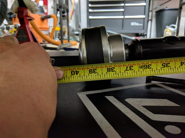
The driveshaft that I received seems to be too long. I only was able to speak to v8 Roadsters a few minutes before they had to be out of office for the week, but It looks like the proper length of the driveshaft should be 36.5 in, whereas mine is about 39.5. I tried just about every way of getting the driveshaft in, and it's not going to work, so I'm assuming the 36.5 is correct, and I was simply sent the wrong driveshaft. I'm really hoping that isn't going to cause too much of a delay, as I really need that in order to get this over to have an exhaust fabbed.
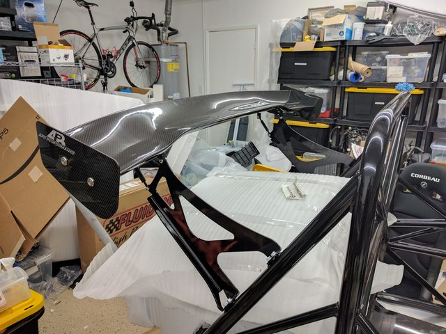
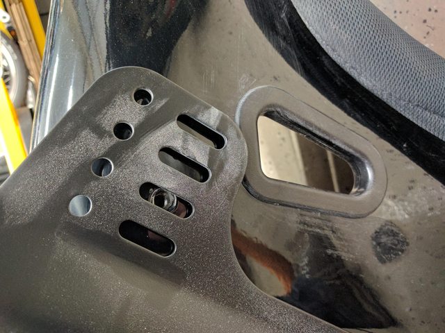
In the meantime while I wait to hear back about the driveshaft, I've been primarily focusing on the drivers seat, brakes, and the wing. APR was amazing and swapped out universal foil for one drilled with the measurements I provided, and machined the custom brackets to fit onto the holes mid transition on the foil. That arrived earlier this week and got put on immediately. A 2D foil would definitely be better for the Exocet, but I had the APR risers as well as the airfoil, and any wing makes the Exocet look way more imposing.
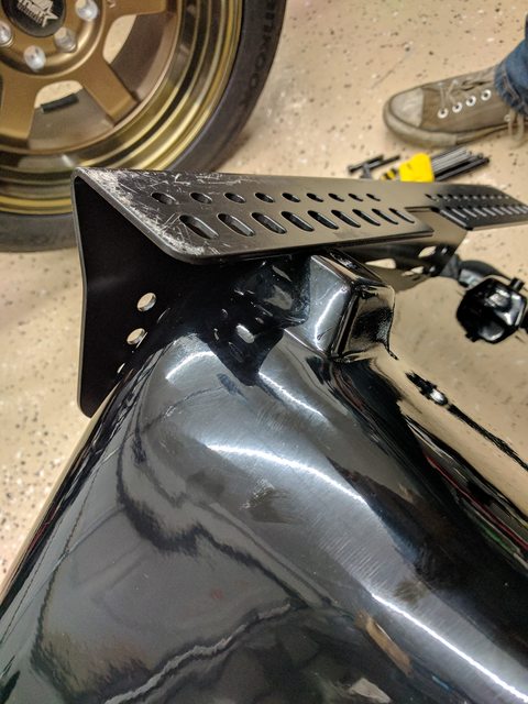
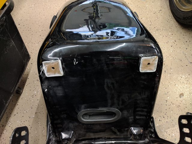
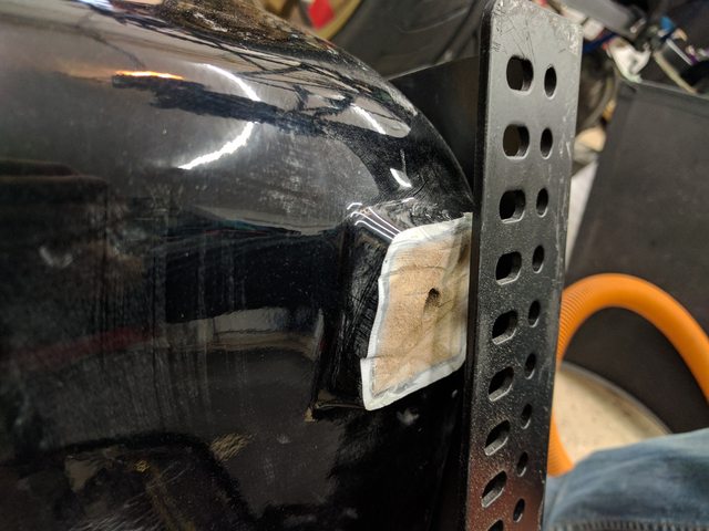
As far as the seat goes, I'm using the Sparco side mount brackets to put some angle into the seat, but I ran into a little issue with the bottom mount feature at the rear preventing me from getting the angle I wanted with the Corbeau FX1 Pro. I'm never going to use bottom mount for these seats, so I opted to shave the rear mounts down rather than boost the front of the side mounts to keep the overall seat height lower. A quick shave later, and the seat is back together with the seat mount and feels way better on the initial test fit. I'm using a crudely made railroad tie looking bracket to lift up the side mount over the lower bent feature of the trans tunnel, allowing me to shift the seat more inboard and have it closer to centered on the steering wheel. I haven't finalized the seating position, but so far my only complaint is how crowded the pedal assembly is against the trans tunnel. I may be able to angle the accelerator pedal closer to the brake to make things a bit more comfortable. I initially had the accelerator pedal mounted closer to the brake, but there's an interference caused by the steering column support bracket and the GM pedal I'm using in particular.
Now that I finally have a good idea of my seat position, I've been test fitting the shifter and found that the linkage is way too short (about 3 inches). It pains me somewhat to have to modify another one, those 3 inches put nearly all of the forward gear selections out of reach with my back on the seat.
With more of the front suspension assembled, I routed the braided brake lines in the front. A bit of mixing and matching was needed with the Exocet kit, as well as the pieces included with the Little Big Brake Kit from Flying Miata. The 10mm to 90 degree -4AN combo caused an interference with one of the bars, so I salvaged one of the banjo fittings originally intended to go on the OEM brakes from the Exocet kit, and used that to make some clearance for the brake line. With all of the lines In front all hooked up, all I have left to do is trim the trans tunnel line and attack the fittings needed to connect it to the prop valve and the T junction at the rear subframe.
Tomorrow I'll be looking to bolt the seat down into its final resting place, and get around to a few small odd jobs that I can do while I wait to hear back about the drive shaft, like mounting the tail lights into the rear body work, and subsequently the bodywork to the chassis so I can get additional measurements as input for the chassis wiring harness design.
The driveshaft that I received seems to be too long. I only was able to speak to v8 Roadsters a few minutes before they had to be out of office for the week, but It looks like the proper length of the driveshaft should be 36.5 in, whereas mine is about 39.5. I tried just about every way of getting the driveshaft in, and it's not going to work, so I'm assuming the 36.5 is correct, and I was simply sent the wrong driveshaft. I'm really hoping that isn't going to cause too much of a delay, as I really need that in order to get this over to have an exhaust fabbed.
In the meantime while I wait to hear back about the driveshaft, I've been primarily focusing on the drivers seat, brakes, and the wing. APR was amazing and swapped out universal foil for one drilled with the measurements I provided, and machined the custom brackets to fit onto the holes mid transition on the foil. That arrived earlier this week and got put on immediately. A 2D foil would definitely be better for the Exocet, but I had the APR risers as well as the airfoil, and any wing makes the Exocet look way more imposing.
As far as the seat goes, I'm using the Sparco side mount brackets to put some angle into the seat, but I ran into a little issue with the bottom mount feature at the rear preventing me from getting the angle I wanted with the Corbeau FX1 Pro. I'm never going to use bottom mount for these seats, so I opted to shave the rear mounts down rather than boost the front of the side mounts to keep the overall seat height lower. A quick shave later, and the seat is back together with the seat mount and feels way better on the initial test fit. I'm using a crudely made railroad tie looking bracket to lift up the side mount over the lower bent feature of the trans tunnel, allowing me to shift the seat more inboard and have it closer to centered on the steering wheel. I haven't finalized the seating position, but so far my only complaint is how crowded the pedal assembly is against the trans tunnel. I may be able to angle the accelerator pedal closer to the brake to make things a bit more comfortable. I initially had the accelerator pedal mounted closer to the brake, but there's an interference caused by the steering column support bracket and the GM pedal I'm using in particular.
Now that I finally have a good idea of my seat position, I've been test fitting the shifter and found that the linkage is way too short (about 3 inches). It pains me somewhat to have to modify another one, those 3 inches put nearly all of the forward gear selections out of reach with my back on the seat.
With more of the front suspension assembled, I routed the braided brake lines in the front. A bit of mixing and matching was needed with the Exocet kit, as well as the pieces included with the Little Big Brake Kit from Flying Miata. The 10mm to 90 degree -4AN combo caused an interference with one of the bars, so I salvaged one of the banjo fittings originally intended to go on the OEM brakes from the Exocet kit, and used that to make some clearance for the brake line. With all of the lines In front all hooked up, all I have left to do is trim the trans tunnel line and attack the fittings needed to connect it to the prop valve and the T junction at the rear subframe.
Tomorrow I'll be looking to bolt the seat down into its final resting place, and get around to a few small odd jobs that I can do while I wait to hear back about the drive shaft, like mounting the tail lights into the rear body work, and subsequently the bodywork to the chassis so I can get additional measurements as input for the chassis wiring harness design.
Reply
2
2
08-08-2017, 07:17 PM
#91
Junior Member
Thread Starter
Join Date: Sep 2016
Location: Concord, CA
Posts: 122
Total Cats: 12

Good news, everyone!
I figured out how to use the existing shifter from V8 roadsters to fit, and I'm actually way happier with it than I would have been otherwise. Instead of mounting the plate on top of the trans tunnel, I flipped it around so the "turret" is angled backwards, and mounted it down about 1" in the front and 1.5" in the back. These all in conjunction put the shifter at a great neutral position, and allowed me use of the shift linkage the v8 roadsters sent. while the angle on the turret isn't technically ideal for shifting, as there will be less forward movement of the linkage when shifting into even gears, it still goes into every gear happily, without hitting any interference.
The 3/8 thread on the shifter limited **** options, but I have a 3/8 to 16mm adapter that should allow me use of a wider range of shift *****.
I finally heard back from PST about the drive shaft, and they're having me ship it out to be adjusted to the proper length, so hopefully that won't take too long to get back in my hands. My first DMV appointment for registration is coming up at the end of the month, and while the car doesn't need to technically be running when I go through the first phase of the SB100 process, I'll only have 90 days afterwards to do all of the required appointments, and I'd really prefer not to reschedule the appointment for a 4th time.
Now the MATG is over, I'm hoping I'll hear back from Exomotive shortly about the replacement Certificate of Origin that the USPS so kindly lost. (the reason my first 3 appointments with the DMV had to be rescheduled).
Last edited by Djwade; 08-09-2017 at 09:44 AM. Reason: Missing Parentheses
Reply
0
0
08-16-2017, 11:59 AM
#92
Junior Member
Thread Starter
Join Date: Sep 2016
Location: Concord, CA
Posts: 122
Total Cats: 12
A few items to update.
First: I'm stupid, and am bad at measuring threads. The threads on the shifter weren't actually 3/8, but rather 10mm. Makes choosing a shift **** way easier.
Second, I finally got the seat halfway bolted in so I can ensure it's sitting straight and I can adjust the position of the steering wheel to be centered on my seated position. Overall I'm really happy with it. The shifter is a smidgen further away that I'd like, but isn't too bad. Regarding the steering rack, When I installed it, I found full lock both left and right, and then installed the steering wheel at the midpoint between the two, however it looks like I've had to adjust one of the steering rod-ends more than the other to get the wheels tracking straight. does the OEM configuration turn more one direction than the other when at full lock?
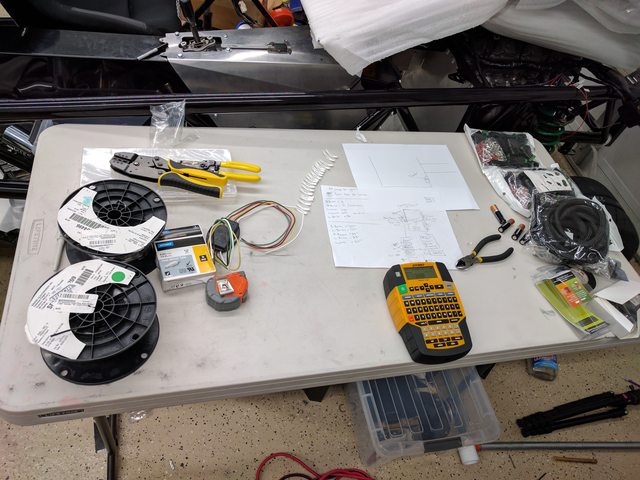
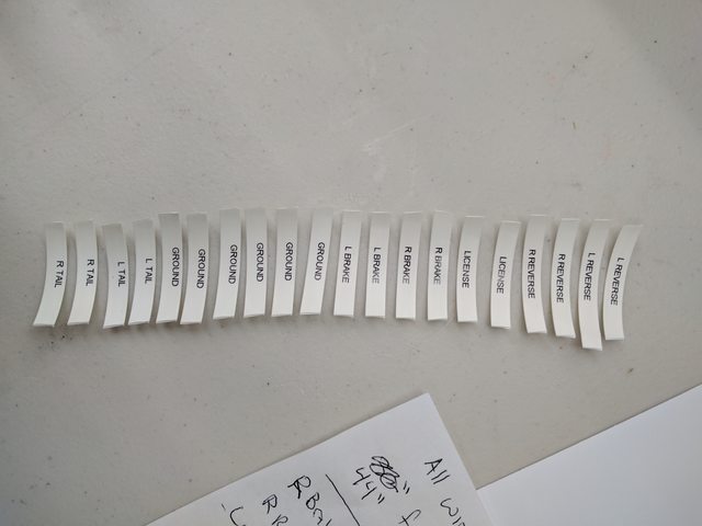
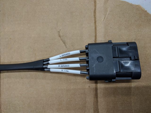
Lastly, I took a page out of ThePass' book and decided to take my time with my chassis wiring harness. Using the same approach of heat-shrink labels and clear heat shrink covering, I began the process of making my rear chassis harness for lighting and fuel pump/gauge. I've added plugs at key points so that when I need to remove the rear bodywork, the wiring for the lights gets removed with it, with the plug disconnecting right at the and of the transmission housing. I still have a lot more to go for the harness, but so far, so good.

First: I'm stupid, and am bad at measuring threads. The threads on the shifter weren't actually 3/8, but rather 10mm. Makes choosing a shift **** way easier.
Second, I finally got the seat halfway bolted in so I can ensure it's sitting straight and I can adjust the position of the steering wheel to be centered on my seated position. Overall I'm really happy with it. The shifter is a smidgen further away that I'd like, but isn't too bad. Regarding the steering rack, When I installed it, I found full lock both left and right, and then installed the steering wheel at the midpoint between the two, however it looks like I've had to adjust one of the steering rod-ends more than the other to get the wheels tracking straight. does the OEM configuration turn more one direction than the other when at full lock?
Lastly, I took a page out of ThePass' book and decided to take my time with my chassis wiring harness. Using the same approach of heat-shrink labels and clear heat shrink covering, I began the process of making my rear chassis harness for lighting and fuel pump/gauge. I've added plugs at key points so that when I need to remove the rear bodywork, the wiring for the lights gets removed with it, with the plug disconnecting right at the and of the transmission housing. I still have a lot more to go for the harness, but so far, so good.
Reply
1
1
08-16-2017, 01:22 PM
#93
Supporting Vendor

iTrader: (3)

Join Date: Jul 2006
Location: San Diego
Posts: 3,303
Total Cats: 1,216
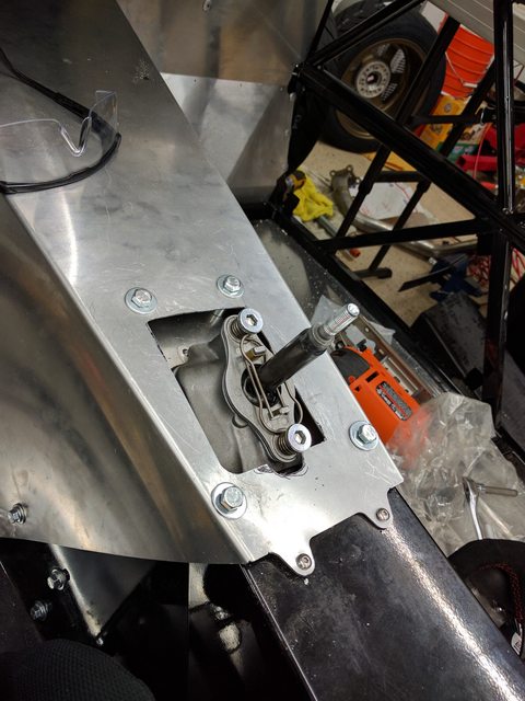
Looking great. You'll be glad you put the time into the wiring, having everything clearly marked and nice and organized pays off huge when working on things later.
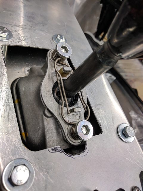
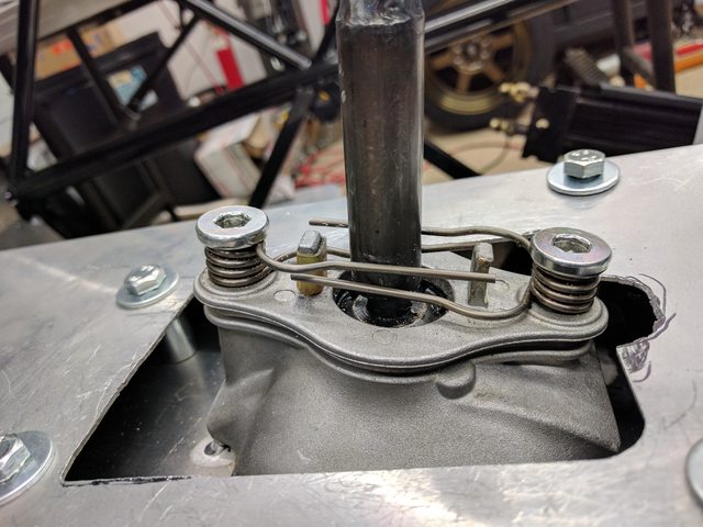
Do you have a closer shot of your shifter? Mine is missing the spring assembly that is strung between the two bolts that I see on yours, and I've been trying to work out why my shifter has a weird feel with more resistance than I'd expect and very little/no return to center in neutral. Those springs look like they assist with that...
Do you have a closer shot of your shifter? Mine is missing the spring assembly that is strung between the two bolts that I see on yours, and I've been trying to work out why my shifter has a weird feel with more resistance than I'd expect and very little/no return to center in neutral. Those springs look like they assist with that...

Reply
0
0
08-16-2017, 08:56 PM
#94
Junior Member
Thread Starter
Join Date: Sep 2016
Location: Concord, CA
Posts: 122
Total Cats: 12
Sure thing. My shifter feels pretty natural, so if yours is missing those, and feels odd, I would wager that's the major difference.
Note there should also be another rubber bumper on that lower post, to prevent the springs from audibly clicking. Mine descided to fall off, so I'll be replacing it with some heat shrink... not that NVH even matters in an exocet, but still feels wrong to leave undone.
I actually have two spare springs from the original shifter that came with my dropout if you want me to send them to you if you don't have them on hand.
Reply
0
0
09-08-2017, 06:21 PM
#95
Junior Member
Thread Starter
Join Date: Sep 2016
Location: Concord, CA
Posts: 122
Total Cats: 12
Update time again!
The driveshaft that was originally too long finally was modified and shipped back. Now that it is finally in place, I can start earnestly preparing for the exhaust to be done. A big remaining component is finally dropping the chassis onto the ground so I can torque all of the bushing bolts. Something new and exciting came up, however, and has delayed that by a week or so, but you won't find me complaining.
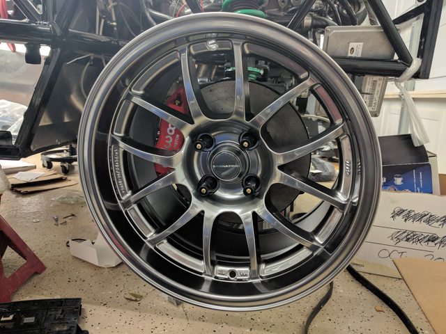
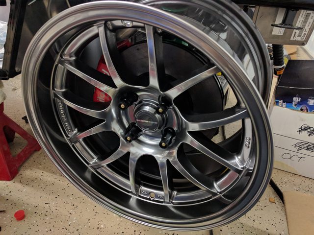
949 Racing released the new, Exocet-specific 15x9 6UL. This came much faster than I expected after they announced the cancellation of the 15x9 Zero 6UL, but I couldn't be happier. Once I found out they were in stock, I immediately ordered a set and sold off my existing wheel set, which fortunately sold quickly.
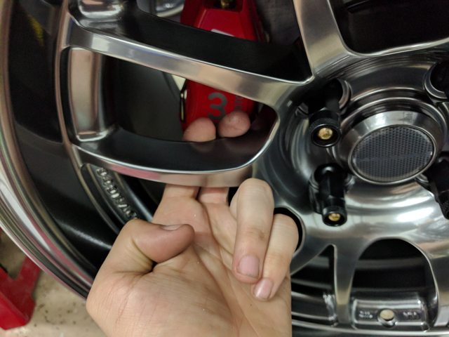
The 6ULs arrived today and they're gorgeous. Massive amounts of brake clearance over the FM little big brake kit, and light-weight to boot. I'm definitely a happy camper, and incredibly thankful that 949 is willing to support a niche kit-car with such an awesome wheel.
The driveshaft that was originally too long finally was modified and shipped back. Now that it is finally in place, I can start earnestly preparing for the exhaust to be done. A big remaining component is finally dropping the chassis onto the ground so I can torque all of the bushing bolts. Something new and exciting came up, however, and has delayed that by a week or so, but you won't find me complaining.
949 Racing released the new, Exocet-specific 15x9 6UL. This came much faster than I expected after they announced the cancellation of the 15x9 Zero 6UL, but I couldn't be happier. Once I found out they were in stock, I immediately ordered a set and sold off my existing wheel set, which fortunately sold quickly.
The 6ULs arrived today and they're gorgeous. Massive amounts of brake clearance over the FM little big brake kit, and light-weight to boot. I'm definitely a happy camper, and incredibly thankful that 949 is willing to support a niche kit-car with such an awesome wheel.
Reply
1
1
 09-15-2017, 12:33 AM
#98
Junior Member
Thread Starter
Join Date: Sep 2016
Location: Concord, CA
Posts: 122
Total Cats: 12
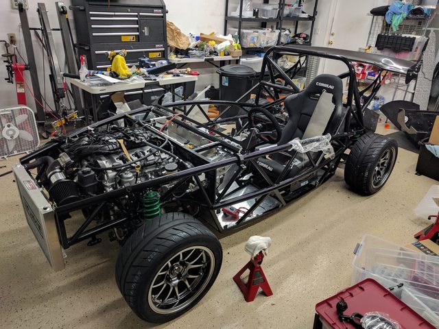
Next week is going to be an eventful week. Monday I head into the DMV for an appointment to get the SB100 process rolling. Tuesday the car gets towed to a local shop for a custom exhaust and a few miscellaneous welding jobs, as well as an alignment. In order to get things ready by then I had to drop it off the jack stands and onto its own wheels so I could torque the bushing bolts. The new Hankook 245/40r15 tires on the 6ULs let me do that. There's a surprising amount of pride that came with getting it on the ground, even if it isn't running yet.
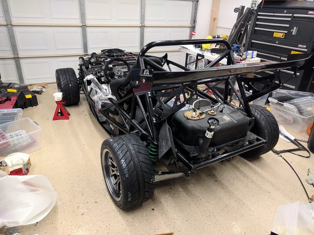
That will come soon. In the meantime, I'm waiting on v8 roadsters to get back up and running after Irma so I can send a few questions their way in regards to wiring. If any of y'all happen to know, it would be greatly appreciated.
In the LFX wiring harness that's been modified, there's a few wires that need to be wired up that I'm not sure about.
The first in question is a wire that's labeled to come from the starter relay. Is this wire simply triggering an internal relay in the starter to then draw from the direct wire from the battery?
The next is a wire that wants +12v from the ignition in the start position. This is the biggest one I have questions about. Instead of start, should this instead be connected to "run"?
Similarly, there's a wire that wants +12V from the battery. Should this actually be wired to the ACC position on the ignition so it only receives 12v when the ignition isn't in lock? Having a constant supply from the battery seems like an easy way to lose charger over time.
Any help with this is sincerely appreciated.
Last edited by Djwade; 09-15-2017 at 11:32 AM.
Reply
0
0
09-15-2017, 04:44 AM
#99
Senior Member

Join Date: May 2007
Location: Atlanta
Posts: 997
Total Cats: 156
I think I can answer a few of these - but I did my own harness so YMMV.
A. Camaro uses a starter relay - once the plug gets energized, it pulls in the solenoid and starter cranks. The miata uses a fat 12gauge cable instead of a relay that goes from the ignition switch through the clutch interlock then out to the starter. In ours I bypassed the interlock for no-clutch starting since it would've interfered with the wilwood master (basically just crimped the two wires that go into the switch together) and then crimped the 12ga wire to the 14ga purple(?) starter solenoid wire in our bussmann RTMR fusebox with a 30 amp fuse between them. It's less fancy than the GM stuff but it works fine.
B. In the miata there's 2 ignition circuits - IG1 and IG2. The difference is that in the "start" position, IG2 gets disconnected. Engine, Meter are your two stock fuses that run off this. Unless it's talking about the powertrain relay, which is memory serves, I used the one of the wires from the coil pack to control. (I tried using as much of the stock fusebox as possible).
C. The 12V battery is probably the memory circuit (Circuit 400 - PITA - I had one wire left over when I did ours that I couldn't identify - turns out this circuit is in the Camaro's Rear fuse box - it's the one Red wire in a sea of pink/black). Yes, you need it unless you want your long term fuel trims to zero out every time you stop the car. I put a 20amp fuse across it.
Reply
1
1
09-15-2017, 07:49 AM
#100
Junior Member
Thread Starter
Join Date: Sep 2016
Location: Concord, CA
Posts: 122
Total Cats: 12
I think I can answer a few of these - but I did my own harness so YMMV.
A. Camaro uses a starter relay - once the plug gets energized, it pulls in the solenoid and starter cranks. The miata uses a fat 12gauge cable instead of a relay that goes from the ignition switch through the clutch interlock then out to the starter. In ours I bypassed the interlock for no-clutch starting since it would've interfered with the wilwood master (basically just crimped the two wires that go into the switch together) and then crimped the 12ga wire to the 14ga purple(?) starter solenoid wire in our bussmann RTMR fusebox with a 30 amp fuse between them. It's less fancy than the GM stuff but it works fine.
B. In the miata there's 2 ignition circuits - IG1 and IG2. The difference is that in the "start" position, IG2 gets disconnected. Engine, Meter are your two stock fuses that run off this. Unless it's talking about the powertrain relay, which is memory serves, I used the one of the wires from the coil pack to control. (I tried using as much of the stock fusebox as possible).
C. The 12V battery is probably the memory circuit (Circuit 400 - PITA - I had one wire left over when I did ours that I couldn't identify - turns out this circuit is in the Camaro's Rear fuse box - it's the one Red wire in a sea of pink/black). Yes, you need it unless you want your long term fuel trims to zero out every time you stop the car. I put a 20amp fuse across it.
A. Camaro uses a starter relay - once the plug gets energized, it pulls in the solenoid and starter cranks. The miata uses a fat 12gauge cable instead of a relay that goes from the ignition switch through the clutch interlock then out to the starter. In ours I bypassed the interlock for no-clutch starting since it would've interfered with the wilwood master (basically just crimped the two wires that go into the switch together) and then crimped the 12ga wire to the 14ga purple(?) starter solenoid wire in our bussmann RTMR fusebox with a 30 amp fuse between them. It's less fancy than the GM stuff but it works fine.
B. In the miata there's 2 ignition circuits - IG1 and IG2. The difference is that in the "start" position, IG2 gets disconnected. Engine, Meter are your two stock fuses that run off this. Unless it's talking about the powertrain relay, which is memory serves, I used the one of the wires from the coil pack to control. (I tried using as much of the stock fusebox as possible).
C. The 12V battery is probably the memory circuit (Circuit 400 - PITA - I had one wire left over when I did ours that I couldn't identify - turns out this circuit is in the Camaro's Rear fuse box - it's the one Red wire in a sea of pink/black). Yes, you need it unless you want your long term fuel trims to zero out every time you stop the car. I put a 20amp fuse across it.
There's a chance that v8 Roadsters used the same wire colors for the ones that need to be connected as they are in the OEM application on the camaro, so I may try to dig up some wiring information to make sure I understand what each wire is doing if I still can't get ahold of them today.
Reply
0
0


