
f20c engine conversion


Reply
 0
0

0

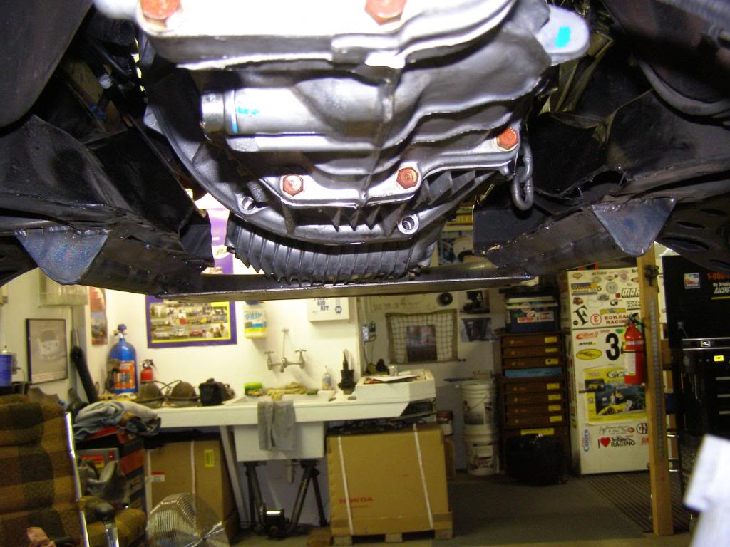
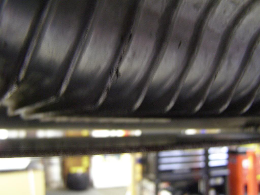
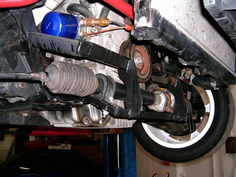
If you look closely you can see the relation of the oil pan to the tube. The tube is roughly 1/2 inch lower than the pan, this along with the skid plate provides protection for the oil pan!
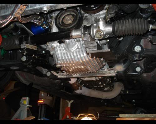
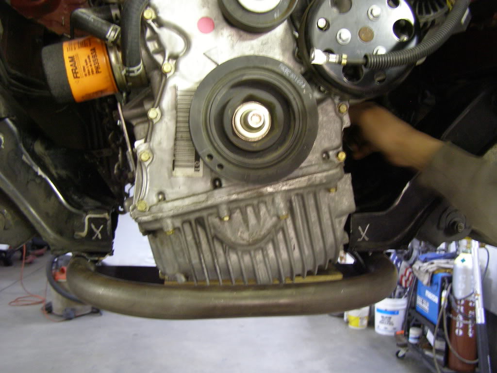
This is a picture from another conversion; same conversion that used the shims to raise the and mount the steering rack. Look at the relation of the bottom of the oil pan to the bottom of the k-member; the oil pan sits well below the k-member, to me this is less than an optimal design. I would much rather have the pan protected by steel than have it be the point of impact if the car were to go off track or bottom through a water crossing. We have all had that happen before
Last edited by hingstonwm; Jan 23, 2010 at 07:55 PM.
Reply
0
0


I have a lot of experience in building things and wrenching on cars, it all started many many moons ago when I took my step fathers 3 speed craftsman snow blower apart.
As I also mentioned, having the opportunity to look over the build pics from another build allowed me to critically think their solutions. Being able to look at a solution to a problem can give great insight as to how to make it better.
Reply
0
0
Ok... this is all coming back to me now. I forgot about the funky oil pump/pickup situation and it creating difficulties for a sump change. This is one swap that would do well with a dry sump.
Reply
0
0

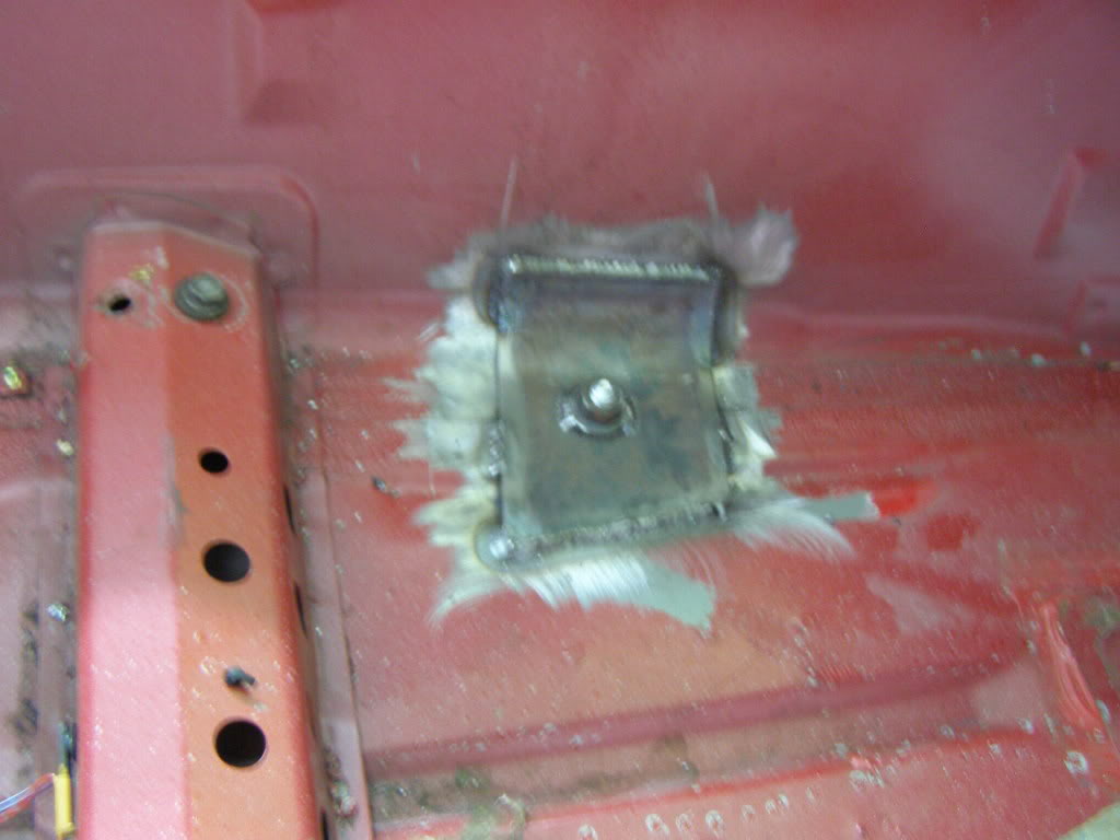
In this picture you will notice that the engine mount is not only broken but mounted in shear....huh I wonder what caused it to fail.
Changing the sump location on the stock pan really is not an option due to the position of the oil pump.
I also figured that honda has guys that are smarter than me getting the oiling system right for this engine, who am I to mess with the design.
Last edited by hingstonwm; Jan 12, 2010 at 02:05 PM.
Reply
0
0

What ratios do the s2000 ring and pinion come in? If 3.6 or 3.9 could be a good place to score a used r&p for the miata. I may have misinterpreted what was being stated. I read that the 1.8 through NB have same R&P as honda s2000.
You should sell these kits if you already have jigs made up for the parts. Granted, you'ed see more people with cars like yours. For those thinking v8 swap, I think this would be a better avenue.
You should sell these kits if you already have jigs made up for the parts. Granted, you'ed see more people with cars like yours. For those thinking v8 swap, I think this would be a better avenue.
Reply
0
0
Very cool, both my parents are RNs. I just saw a good amount of engineering in your work, figured you might be an engineer haha.
Well, hopefully an RN, i take my state boards in 11 days (but who's counting!).
I have a lot of experience in building things and wrenching on cars, it all started many many moons ago when I took my step fathers 3 speed craftsman snow blower apart.
As I also mentioned, having the opportunity to look over the build pics from another build allowed me to critically think their solutions. Being able to look at a solution to a problem can give great insight as to how to make it better.
Reply
0
0
The engineering ability comes from my experience working on cars and critical thinking. We have all cussed the designers at one point or another and said why didn't they do it this way...or I wish they had designed it like this. So here is my opportunity to make some of "I Wish" happen!
Reply
0
0

OP, the progress looks amazing! In for more pics!
Reply
0
0
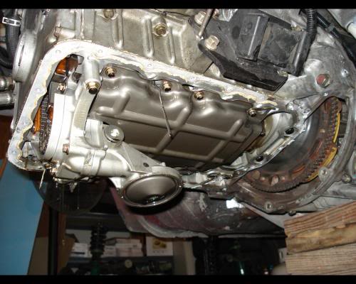
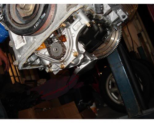
I found a better picture showing the relation of the crank girdle (don't know why I was calling it a cradle) and the k-member, I believe this pic shows how a dry sump would not eliminate the k-member modification needed to fit the engine. If you look closely you can see the wood I used as a spacer between the oil pan and the skid plate to obtain the engine ride height that I wanted.

In this picture you can clearly see the crank girdle that bolts to the bottom of the block and carries the lower main bearings
On a side note, there have been 4 f20c conversions into miatas that I know about including mine. One has been disassembled (the one with all the shims locating the steering rack). When I was researching the conversion I came across a couple other pictures of steering rack mounts. I thought I would post them here so you could see the other approaches taken.

The above two pictures belong to the original f20c into a miata conversion, torik is the name of the builder, the car was sold to a 2nd party who gutted it and made it a track car, the last i heard it was up for sale. The car was featured in Super Street magazine, it is what first got me thinking about doing the conversion myself.
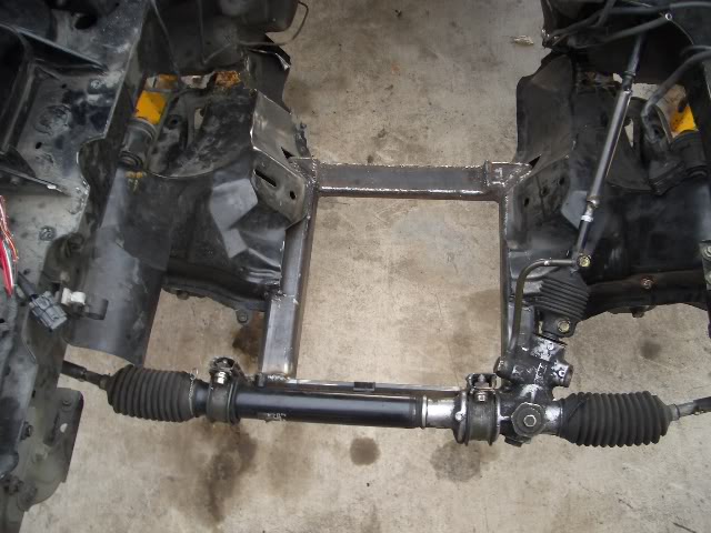
This is a little better but box tubing and 90 degree angles are not as strong as my design. not to mention the fact that this approach will leave the cast aluminum oil pan as the lowest point on the front of the car and vulnerable to impacts. Furthermore, it looks to me that fatigue could become an issue with this design as there does not appear to be great attachment betwwen the existing k-member and the square tubing
Reply
0
0

Me so horny...me love you long time.
I can only hope that your review of the completed car is as thorough as your build so it helps more of the interested take the plunge. Absolutely great craftsmanship, and a good way to work around some of the problems (sometimes by trial and error).
When I picked this car up 2yrs ago with a blown 1.6L I REALLY wanted to swap something into it. After getting flamed on m.net I came over here and went turbo...but I've still got an itch there that needs to be scratched.
I know the LSx swap is a proven, effective, and well paved route that has a lot of bang for the buck...but I still enjoy seeing the one-offs..and it's hard not to grin when you think about an SR20, F20C, 13B or even a 2JZ in a Miata.
Kudos.
Reply
0
0
Engine mounts were pretty straight forward to fabricate. I had the engine and transmission located in the car where I wanted them. The engine was sitting on wood spacers located on top of the skid plate and also supported by a hoist. plates were fabricated and bolted to the engine. Then the rubber engine mounts were bolted to the subframe, and a plates bolted to them. After this was done, I used a file folder and cut template that fit between the plate on the engine and the plate on the engine mount. All that was needed at this point was to transfer the pattern to plate steel cut out the pieces, tack them into place and weld them up.
Reply
0
0
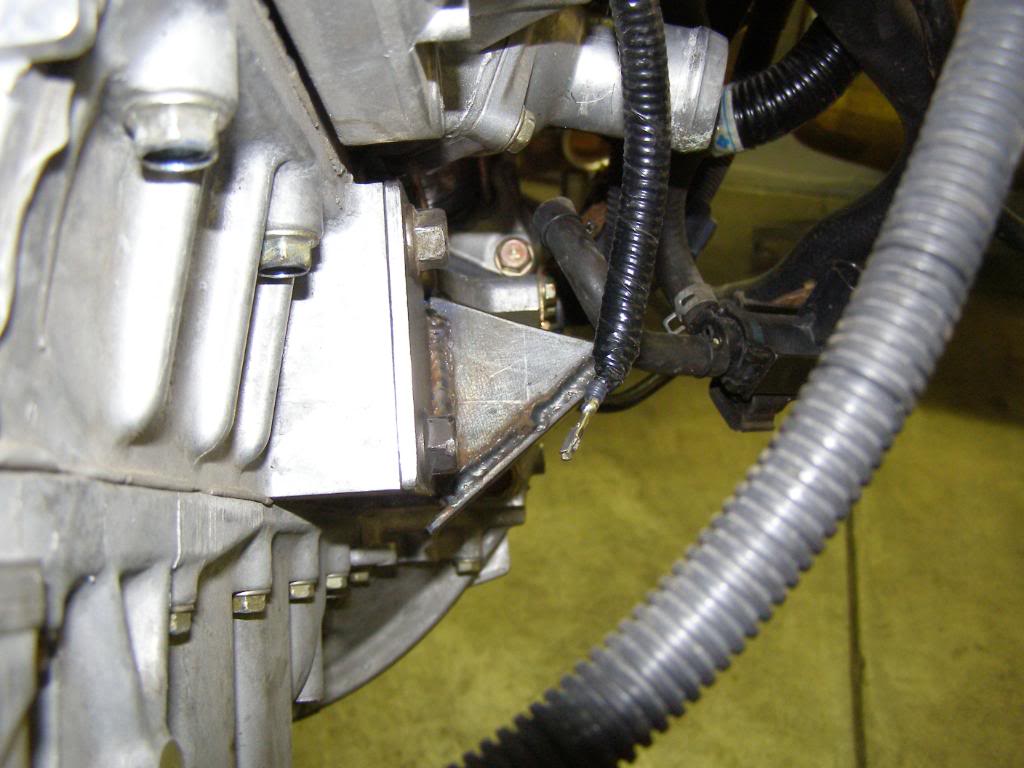
Time for the transmission mount, almost every conversion I have seen in a Miata has utilized the unibody frame stiffeners for mounting the transmission. Personally, I don�t like this approach and I believe that the mount that we have come up with is structurally stronger and probably the simplest. Our design allows for the use of the stock transmission mount on our cross member. The set up is no lower than the bottom of the existing unibody stiffeners.
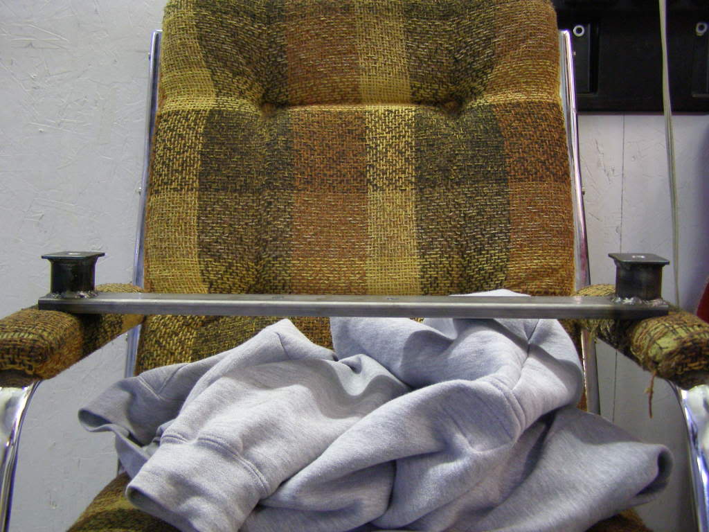
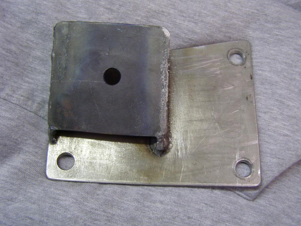
A very simple design for the cross member: .125 C-channel 1.5 inch .120 wall tubing and .125 plate. The cross member has a couple of holes drilled in it to accept the stock transmission mounting bracket. The advantage of using tubing on end is that it will not crush.
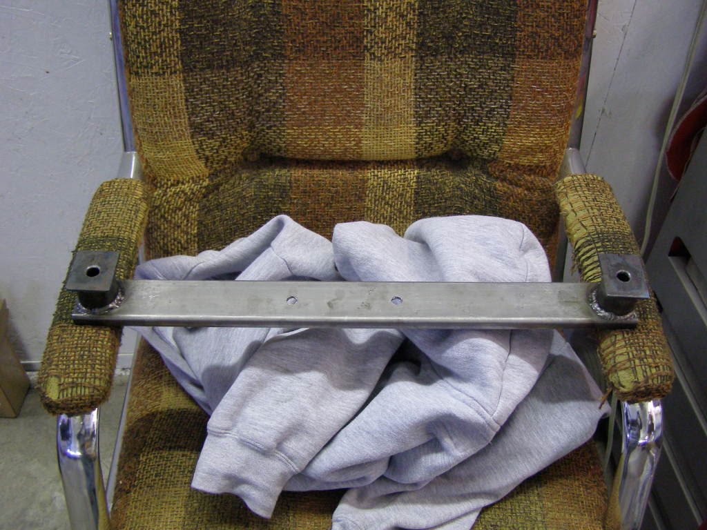
From this angle you can see the bolt holes for mounting to the chassis and the holes in for the stock transmission bracket.
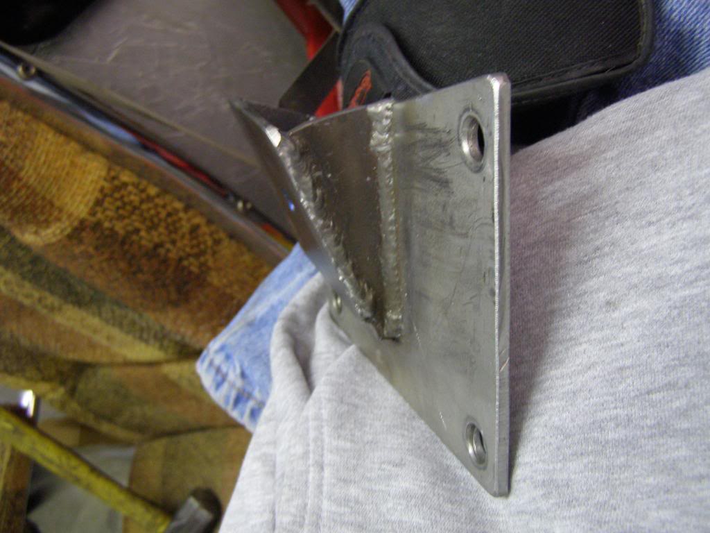
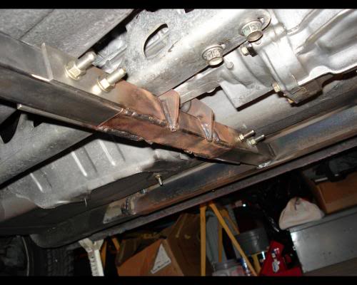
It wouldn�t be strong enough to just bolt the cross member to the floor so we added these plates. Notice that the plates are in two planes as the plate is also welded to the transmission tunnel. This design will be plenty strong.
The plates are mounted just forward of the front seat riser/mount. There will be a small bulge under the carpet, but with the location so close to the front of the seats it won�t be noticeable
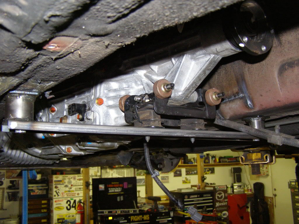
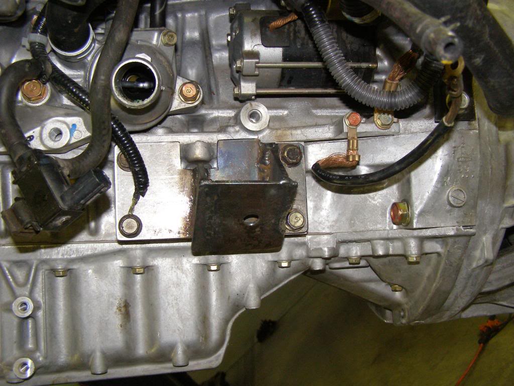
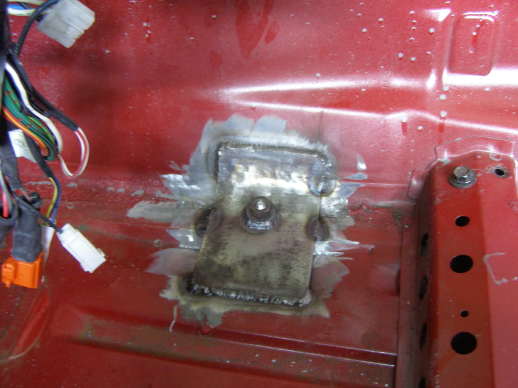
In this shot you can see how the stock transmission mount is incorporated into the transmission sub frame. I have new rubber for the mounts if you look closely you can see that the rubber closest to the camera is torn
This is typical of the sub frame and transmission mounts that I have found in other engine conversions, not only S2k conversions but V-8 conversions as well. There is some sort of mount that attach�s to the unibody stiffener, then box construction extends across the car and the transmission attaches in some fashion using a transmission mount. The cross member is alright but is in shear, and can sag no matter how much torque is applied to the mounting bolts. I like our design much better.
A very simple design for the cross member: .125 C-channel 1.5 inch .120 wall tubing and .125 plate. The cross member has a couple of holes drilled in it to accept the stock transmission mounting bracket. The advantage of using tubing on end is that it will not crush.
From this angle you can see the bolt holes for mounting to the chassis and the holes in for the stock transmission bracket.
It wouldn�t be strong enough to just bolt the cross member to the floor so we added these plates. Notice that the plates are in two planes as the plate is also welded to the transmission tunnel. This design will be plenty strong.
The plates are mounted just forward of the front seat riser/mount. There will be a small bulge under the carpet, but with the location so close to the front of the seats it won�t be noticeable
In this shot you can see how the stock transmission mount is incorporated into the transmission sub frame. I have new rubber for the mounts if you look closely you can see that the rubber closest to the camera is torn
This is typical of the sub frame and transmission mounts that I have found in other engine conversions, not only S2k conversions but V-8 conversions as well. There is some sort of mount that attach�s to the unibody stiffener, then box construction extends across the car and the transmission attaches in some fashion using a transmission mount. The cross member is alright but is in shear, and can sag no matter how much torque is applied to the mounting bolts. I like our design much better.
Reply
0
0
 I like this a lot! Another thread I missed. F20 engine is a masterpiece.
NA6Cguy
i love the black deck spoiler and filler panel, great idea. i am planning on painting my car yellow once all of my mechanical work is complete. I plan on using you black paint work on my car.
i love the black deck spoiler and filler panel, great idea. i am planning on painting my car yellow once all of my mechanical work is complete. I plan on using you black paint work on my car.
Reply
0
0
Thanks. I recently repainted the panel to matching red, but I miss the black so I may be taking my good paint job and rattle canning over it again. Looks kind of weird with new classic red with the 16 year old classic red. They don't exactly match.
Reply
0
0


