When you click on links to various merchants on this site and make a purchase, this can result in this site earning a commission. Affiliate programs and affiliations include, but are not limited to, the eBay Partner Network.
Thanks for the idea! I wish I could put the ECU in the cabin. Unfortunately, Chevy pretty much dictates that the ECU has to be in the Engine Bay on the passenger side right behind the headlight. I'm sure someone has moved it by now, but it would require elongating the harness and I'd guess that would be somewhere around 100 wires you would have to elongate.
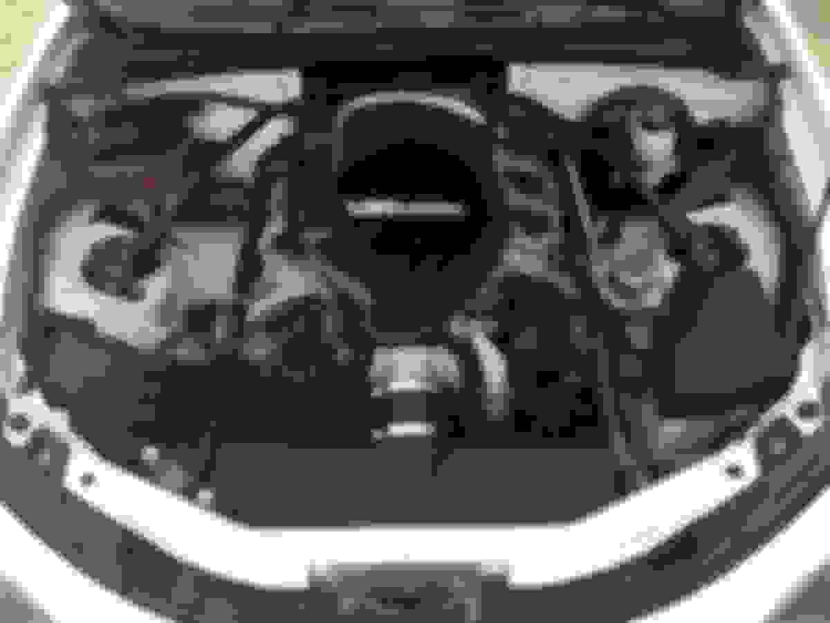
Here's a picture of an NC with an LFX swap that I stole from the V8Roadsters site. I think they did a good job of keeping it all looking pretty clean.
I'm sort of jumping around here a little bit. (but isn't that normal for a build? waiting on a part, not feeling something, etc. so work on something else?) I actually did the control arms over a month or so in the middle of seam welding and removing the rear subframe etc. but I'm going to list it all in here like I did it all at the same time since it's done, and it makes everything a bit more coherent.
For the suspension, I purchased the SuperMiata Big Grip Kit with all the bells and whistle. (I actually bought this kit on Black Friday, almost 2 months before I purchased the car or decided upon the LFX build. At that time, I still looking at different builds, but I was heavily leaning towards the TSE turbo kit.) Anyway...This kit comes with Poly Bushings for the control arms. Shortly after purchasing all of the above, I learned about Sadfab's products and ordered up their bearing kit. If I was to do this over, I think I would have just gone with the Sadfab's derlin bushings since race car, but I'm really excited to try out what I have, and not upset with my choices at all.
Removing all the Rubber Bushing
I hate looking like Pigpen within 3 minutes of being down in the garage & these guys will definitely make you dirty. A quick wash and I was pleasantly surprised at how good these looked once cleaned. I ended up spraying some rustoleum on a couple of them, (The bottoms of the Rear lowers if memory serves) but most just got washed and looked almost new.
OK, onto the actual removal of bushings...
There are basically 3 different ways to do this. Burn them out (which would thrill my HOA & make my neighbors so happy!), press them out with a shop press, or press them out with some threaded rod, nuts, washers, and a piece of pipe. I used the threaded rod & pipe for a couple bushings and decided there must be a better way...so I went out and bought a shop press. Besides, I would need the shop press for pressing the hubs and bearings that will need to be replaced too. (LOL...give me just one little iota of an excuse to buy a new tool!)
The press worked well for some of the bushings, but I had a hard time getting some of the others all lined up. Ultimately I ended up using the threaded rod & pipe method for over half of these guys. I used my impact gun to help speed things along, but it's a slog either way.
I feel like removing control arm bushings has been covered ad nauseam, so I'll keep this brief with just a few tips below. FYI...You can find info on removing the bushings from Greg Peters / The Car Passion Channel on Youtube, or the SadFab directions show you how to do this too.
Some tips:
I bent & stretched threads on more than one piece of threaded rod doing all of this. If you can find Grade 8, I'd use that. Same with the washers & nuts.
I used 1.5" X 3" piece of black pipe from Lowes Racing Supply.
I welded on a huge thick washer at the end of the pipe, this helps keep you from having to stop and adjust things as much, since it can't slip off.
Installing Grease Fittings for Bushings
Installing the grease fittings isn't too bad, the hardest part is figuring out the alphabet soup...RUCA-O, FUCA, FLCA-R, etc. Since all these acronyms look the same this is definitely a measure twice cut once sort of thing.
I used the SadFab instructions and the instructions from SuperMiata / 949 Racing.
Basically, the grease fitting needs to go in the middle between the two bushings, and you don't want the fitting getting guillotined off when going through it's range of motion. Note: If you buy the SadFab kit, it includes the grease fittings you need, otherwise you will need to go purchase yourself.
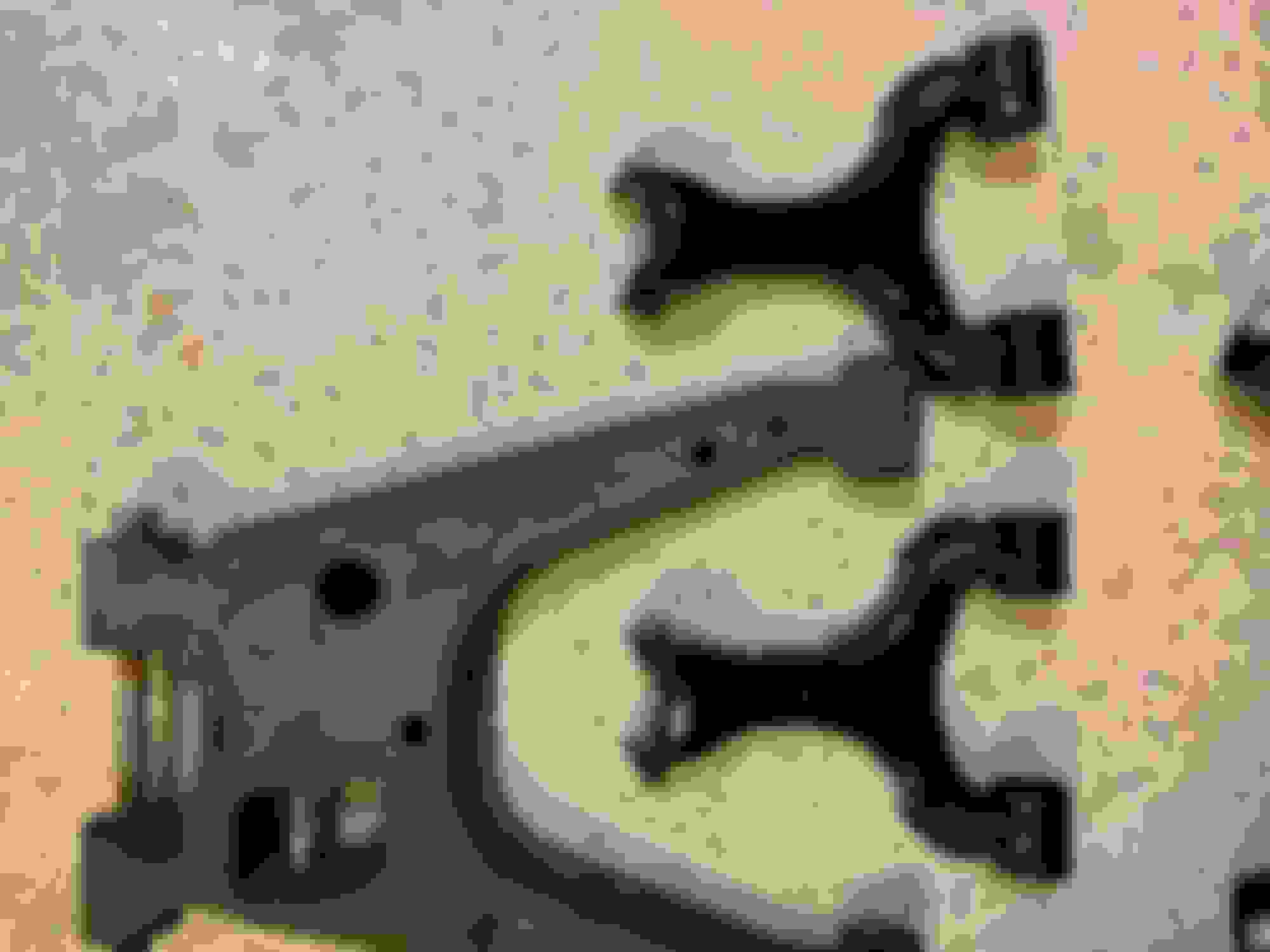
Drill a hole in the proper spot (don't mind that second hole, that was already in the control arm, it's in the wrong place & we will get to that in a second)
Tap the hole...(if you have never done this before, I suggest you use some cutting oil on the tap. I also use cutting oil on my drill bits when drilling metal. Makes your cutting tools last longer and cut easier.)
Some of the control arms have a hole already drilled in them thats in the wrong place so you can't use it. For those I just welded them close. I used a 1" copper plumbing coupler. It worked great at keeping the back of the weld flush.
Install the grease fitting. I used some pipe dope on these too.
Installing the Bushings & Bearings
BEFORE you do anything...Make certain you are well stocked in Mineral Spirits and disposable gloves. If not, go buy both...Then, so you don't forget, put on the disposable gloves immediately. Seriously, the HyperLub that you use to grease these things does NOT wash off and it gets on EVERYTHING. You have been warned! (6 months later and I still get it on me from time to time!) As a tangent, there is one other great purpose for HyperLub besides just greasing your poly bushings. <Evil Voice> May I suggest a nice smear of HyperLub under that someone specials car door handle. It's a gift that WILL keep on giving! </Evil Voice>
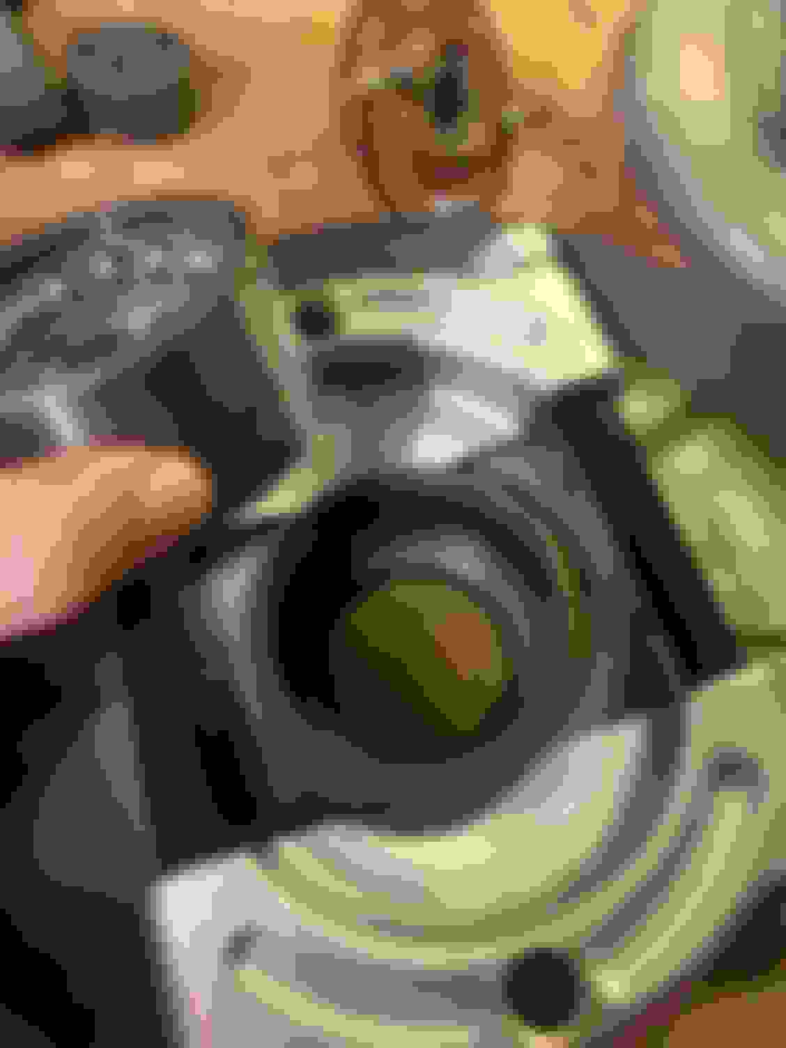
Alright...here is a shot of the bearings we are going to install along with the bushings. SadFab nicely labeled all of them. The rubber bushings all have numbers on them, so you know what goes where using their directions.
The bushings come with a diagram that shows where each one goes. I found it easiest to install the sleeve into the bushing before pressing the bushing into the control arm (don't forget to push the sleeve in far enough for the washer too). Although everything is greased up, it was almost impossible to install the sleeve after the bushing was in the control arm. Additionally (because we want to get this grease on EVERYTHING) I used my vice / a clamp to press the bushing into the control arms if I couldn't press them all the way in by hand. I don't have any action shots of doing this...because of the HyperLub, but here's a nice done shot.
So...even wearing gloves and trying your best the Hyperlub got everywhere? How do you get it off everything? I'll share the secret. (Just don't share it with the door handle guy) Good Luck!
I'm super impressed with the SadFab bearings. It's beyond easy to move the control arms up and down when they are attached to the subframe. I would never be able to do this with rubber bushings and seriously doubt with the poly greased up either. Check out the video below to see how easily they move.
You're going to like the Sadfab kit. I've got full delrin and it's awesome. About the same "resistance" as yours has even after some track miles. One thing about that hyperlube though, when I removed all my poly bushings to install the delrin, that stuff had turned to almost like a contact cement and had glued a bunch of stuff together. Had to use a press with a decent amount of force to remove the poly bushings and normal solid inserts. I also didn't have zerk fittings so that will probably save you, after the first outing I would just pump a bunch of normal synthetic grease through there to flush out any that is in a bad spot. I would have skipped that nasty **** and just used a nice synthetic grease instead if I were to do that over again.
@Arca-ex — the hyperlube turning into a solid mess was one of the other things that made me want to move to the derlin. I did a little reading and was thinking about using a normal synthetic, but some (don’t remember who, 949 racing maybe? but I obviously thought whoever knew what they were talking about) said the synthetic grease was a bad choice for the bushings and to use hyperlube or super lube because it’s silicon based and isn’t bad for them. I figured I’d get a little grease gun just for the super lube and use that...If this all doesn’t work, just an excuse to get those derlin bushings! Ha!
@Satisaii — I normally try “weaker” chemicals and work my way up, but I think I started with Mineral Spirits right off the bat and didn’t even try WD40. I’ll give it a go next time. Thanks for the info!
20 year old car with original OEM Suspension parts…time to replace those ball joints & tie rods.
Upper Ball Joints
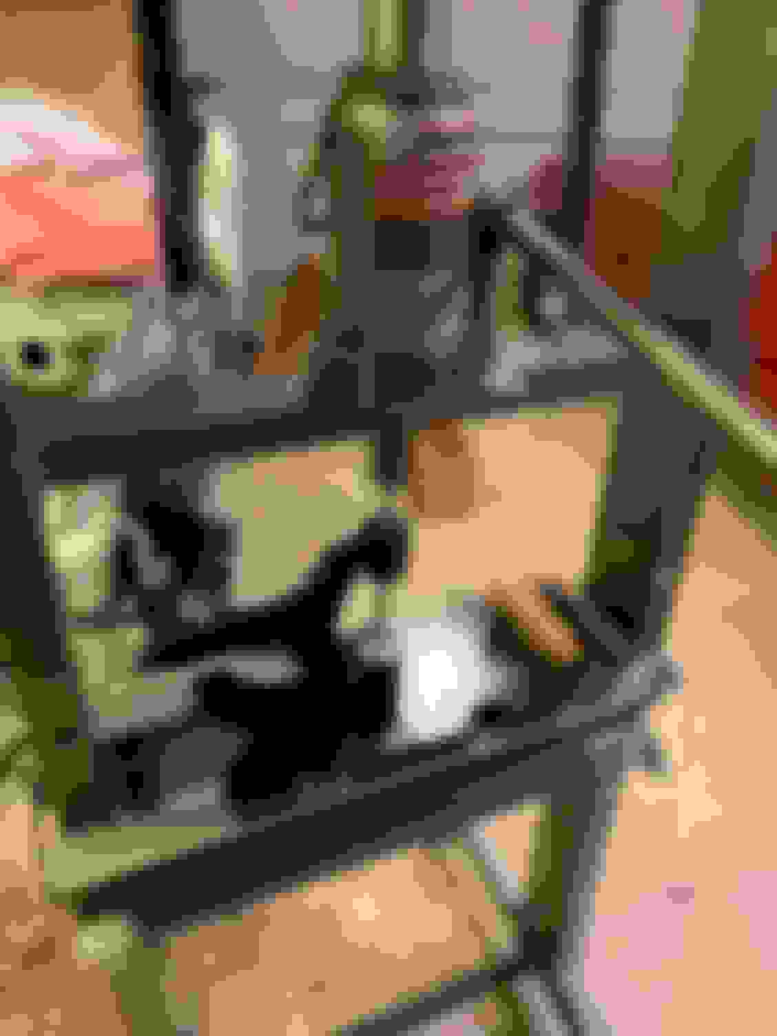
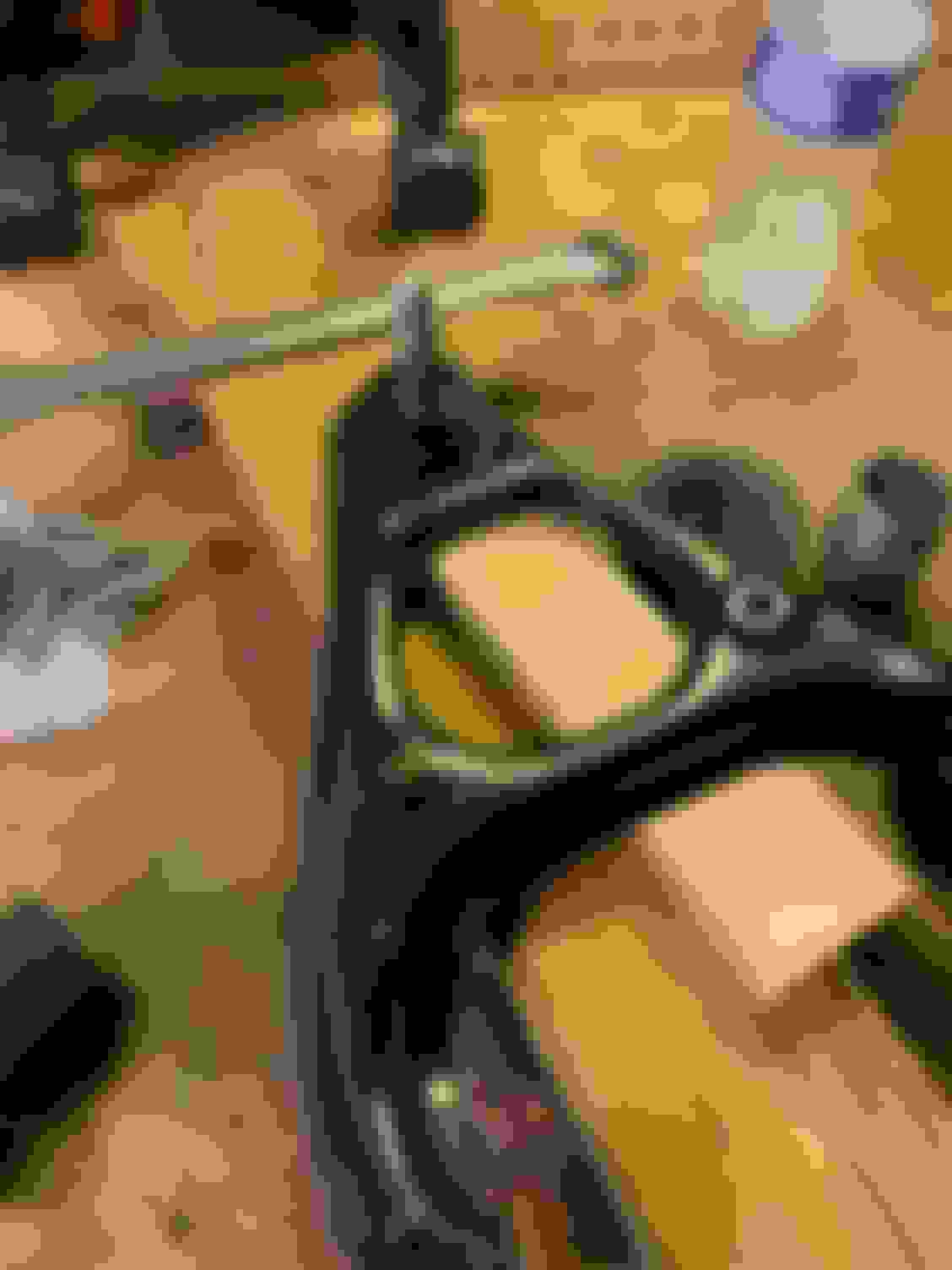
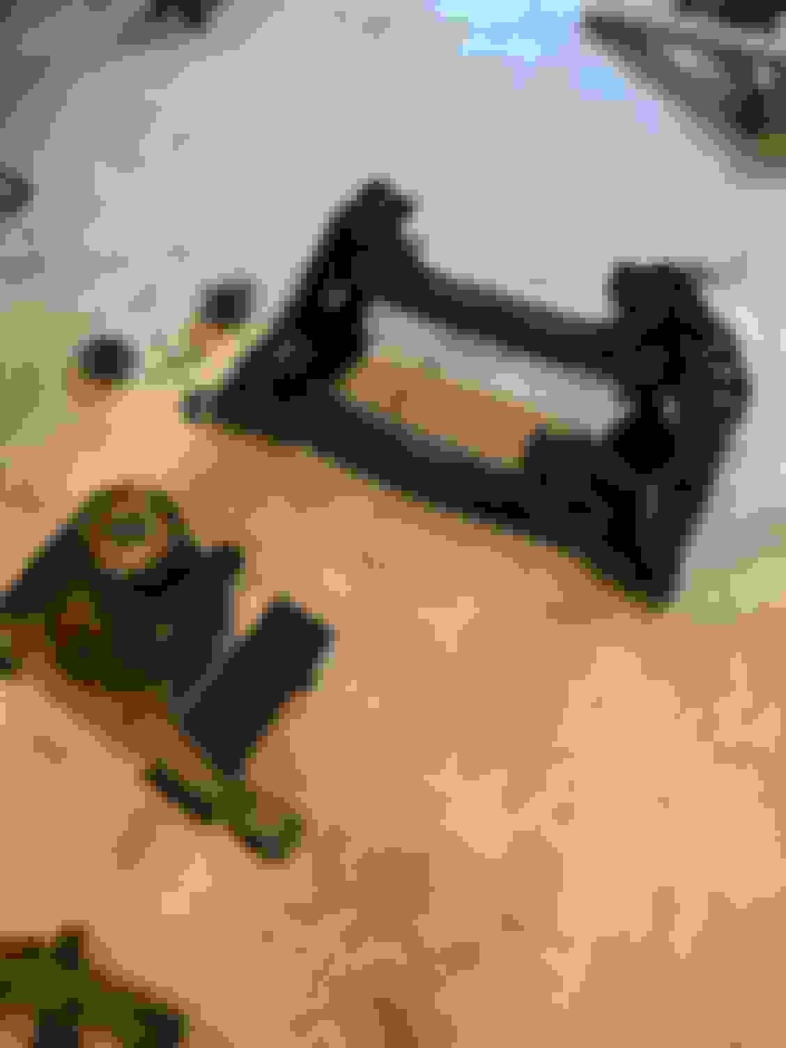
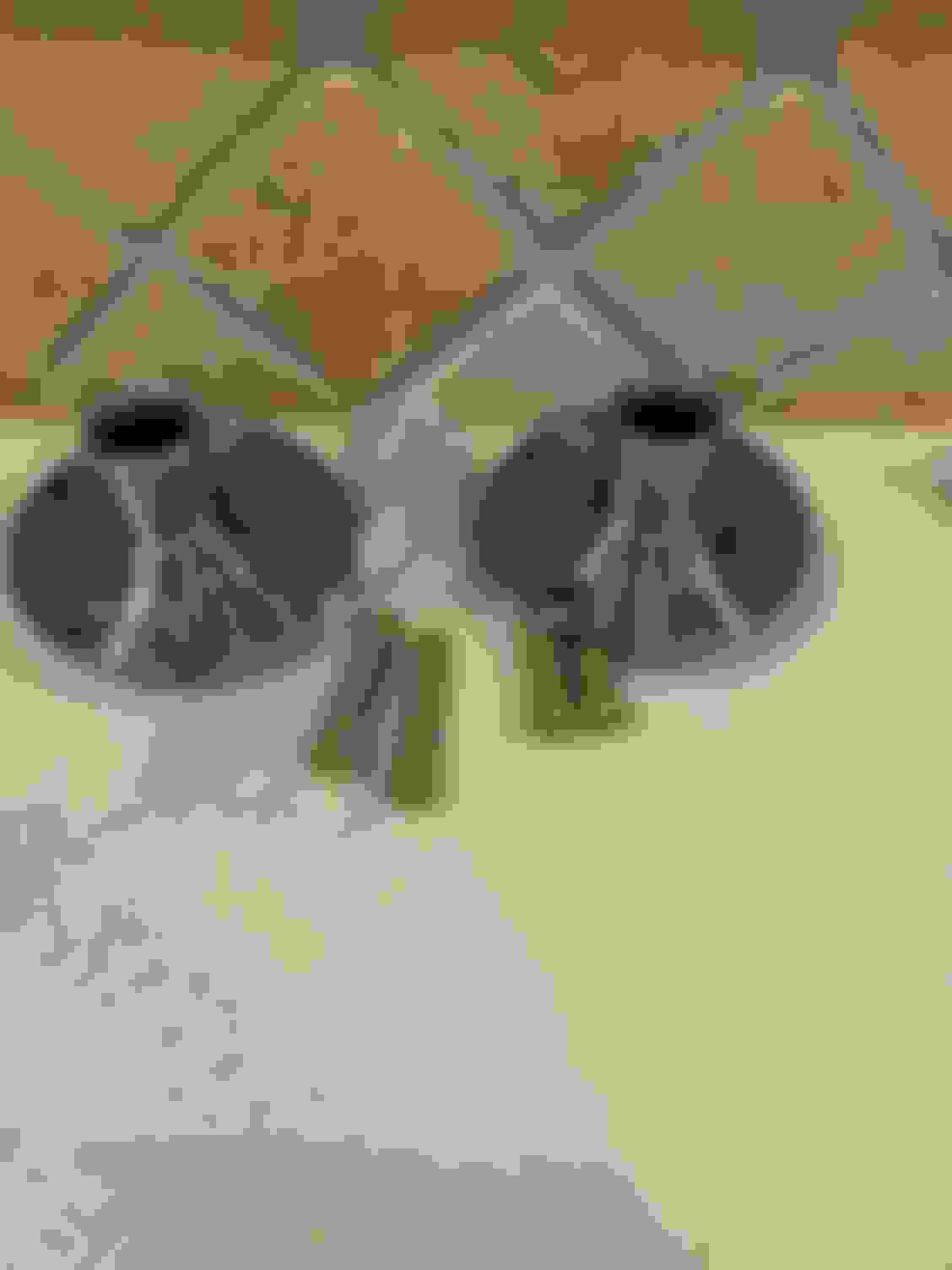
First I had to press out the old ball joints, using a ball joint press that a buddy lent me. Like all "pressing" it's a pain to get everything lined up so things go in straight, especially when you are using "universal" tools that don't exactly fit. Using my small vice to hold the clamp and some boards to prop up the back got everything lined up for me.
Then, easy as pie, just reverse it and press in the new Upper Ball Joint.
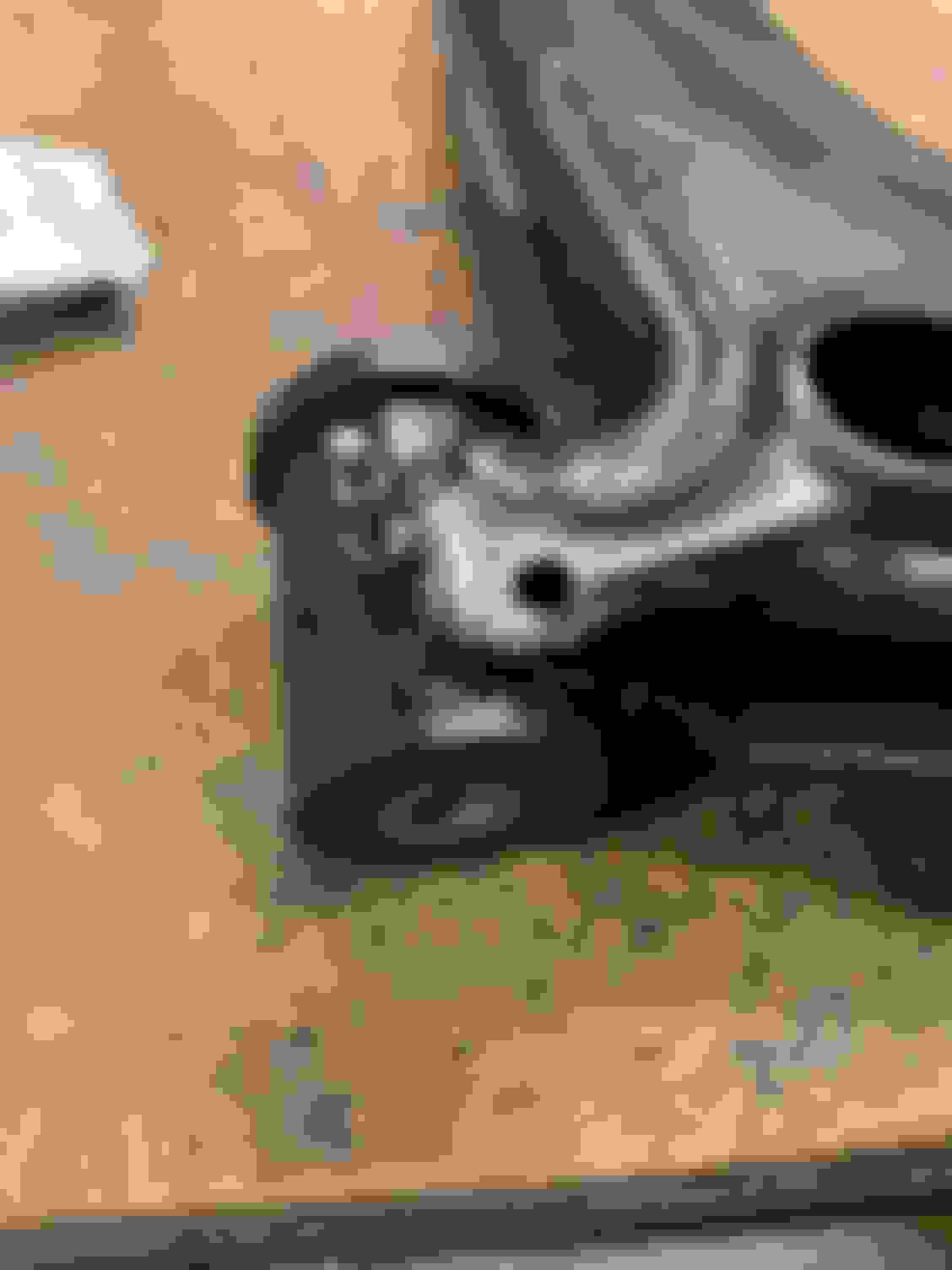
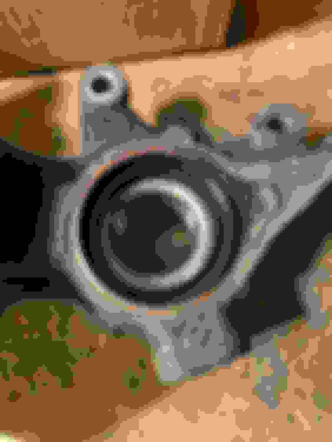
And you're left with this master piece...
Notice anything "Special" about this? Don't feel bad if you don't first see it, it took me zooming in to snap a picture of my awesome handy work before seeing it. Yup, that ball joint is pointed in the wrong direction! I wish I could say I was drinking, but the photo reveals all of my stupidity without allowing any wiggle room for a saving face lie.
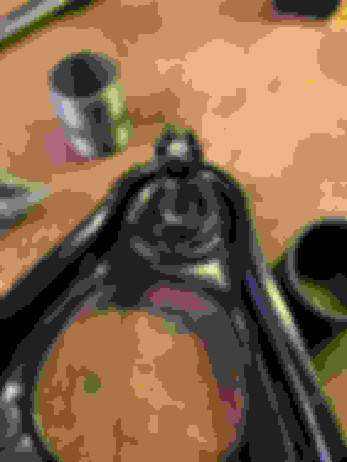
Obviously I was having so much fun, I wanted to do things again...so after rinsing and repeating, we ended up here. Finally!
I'm wondering if I should put a little tack weld on each of these, but I'm thinking the snap ring should help hold them in place. Anyone else have thoughts on this?
Lower Ball Joints
These might just be the easiest Ball Joints to replace in the world. Remove cotter pin & castle nut. Separate the ball joint from the spindle. (Note, in past lives I would either use a pickle fork or try hammering the side to break it free, both eventually work, but neither work as nicely as a ball joint separator tool. You can pick these up cheap at Harbor Freight for under 20 bucks.) Then remove the two bolts and Voila! It's out. I installed the Extended Lower Ball Joints to get some more Camber when the time comes.
Tie Rods
I just changed over the Outer Tie Rods and left the inners alone (actually, I end up removing the inners later, but they seemed fine and I didn't replace). I purchased the forged outer tie rods thinking they were also the R Package ones, but after more review, these aren't those. So...they are on the car for now, but I'll eventually change them out. Since EVERYTHING is changing on the car, including the front subframe, I didn't bother to record how many turns to get the alignment close. I'm sure when I go to do the rough alignment it will all be off, but for now, I just screwed them on and job done! I didn't take a photo while doing this, but I can't leave without another photo, so here's one of the outer tie rod that will resurface soon when we discuss the brakes.
Note: I don't have cotter pins on any of the castle nuts, everything is hand tight for right now since I figured things might need to come apart again for various reasons.
Up next...I'll start documenting all the changes to the rear end / diff.
Last edited by rdb138; Oct 19, 2020 at 03:05 PM.
Reason: I don't know the difference between your and you're
It's been a busy last couple of weeks, (brother got married & interviewing for jobs) but I didn't fall off the build thread wagon. I pretty much had the car all apart except the rear end. I left it in the car till last because it made it easier to roll the car around in the garage and I only had so much room to store items, but the time had come. So after removing the bolts holding the shocks & the 6 bolts on the bottom, I lowered the whole assemble down onto two dollies.
Things kept coming apart quickly, brakes, shocks, sway bar, all the way up to the hubs. The half shafts did not want to release from the hubs. I was trying to "gently" remove the hubs from the half shafts so I could sell the torsen & parts later. I decided to run to the parts store to rent a hub removal too. Of course the store near me didn't have all the parts and sent me down the road, which did have the tool. It was one of the attach to the wheel studs and press out type. Unfortunately once I got home, I realized it was too big to fit the Miata 4x100 studs. OK, I'll just return it and go to a different parts store and rent there tool. This time I got a slide hammer version, and it looked like it was going to do the job perfectly...that was until I got home and figured out again, the Miata 4x100 wheel studs were too small for this tool too. Small Car Problems! Grrr...after wasting 3 hours renting tools that don't work, I was a bit irritated. So, I did what all of us neanderthals do in this situation and pulled out the BFH. I carefully screwed the old nut previously holding the half shaft to the hub flush onto the threads to help keep from destroying them and beat the half shafts into submission. The BFH method was successful, but I still mess up threads a bit on one of the half shafts. Note to self...Use anti-seize on the spline of the new half shafts!
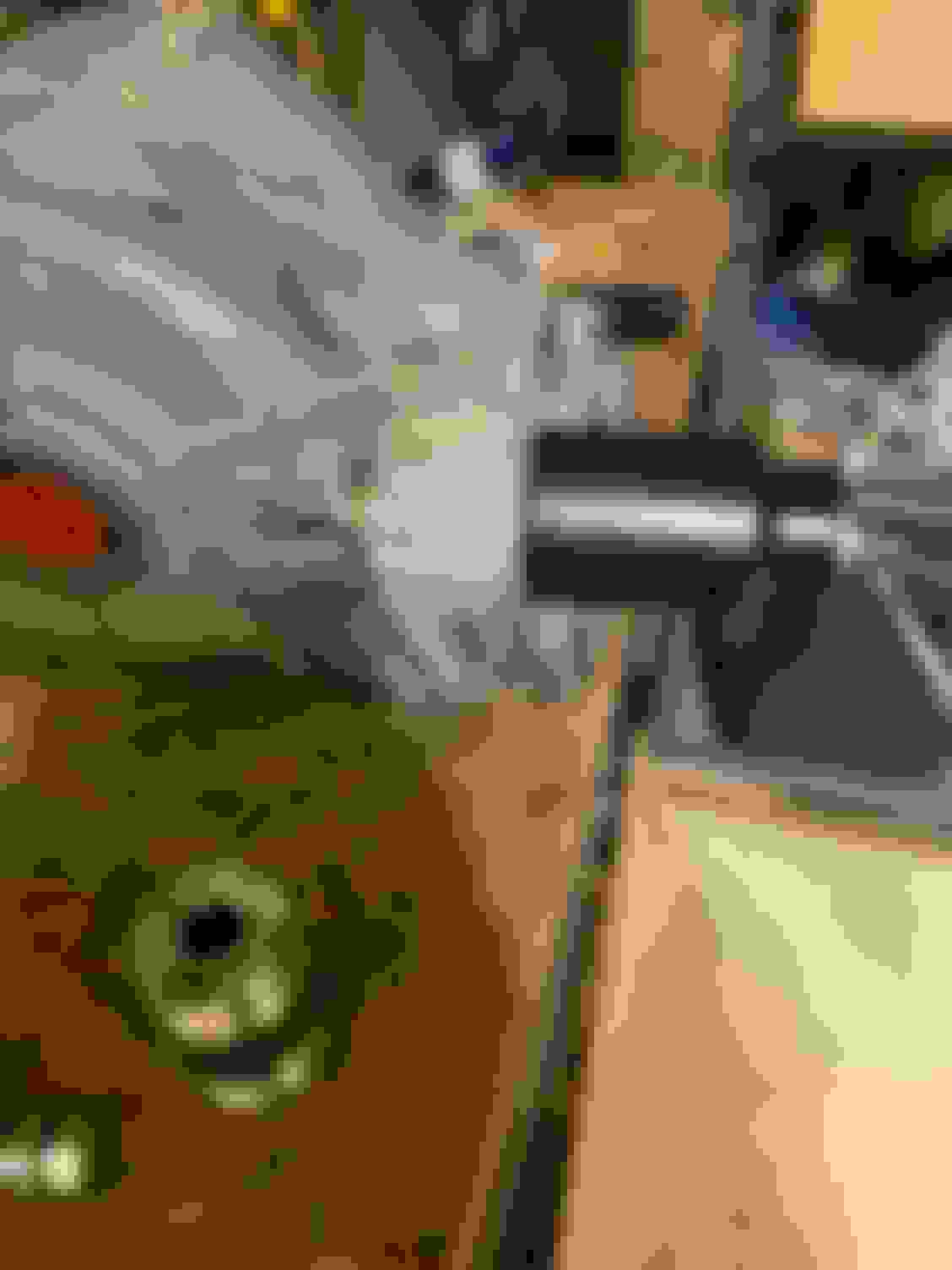
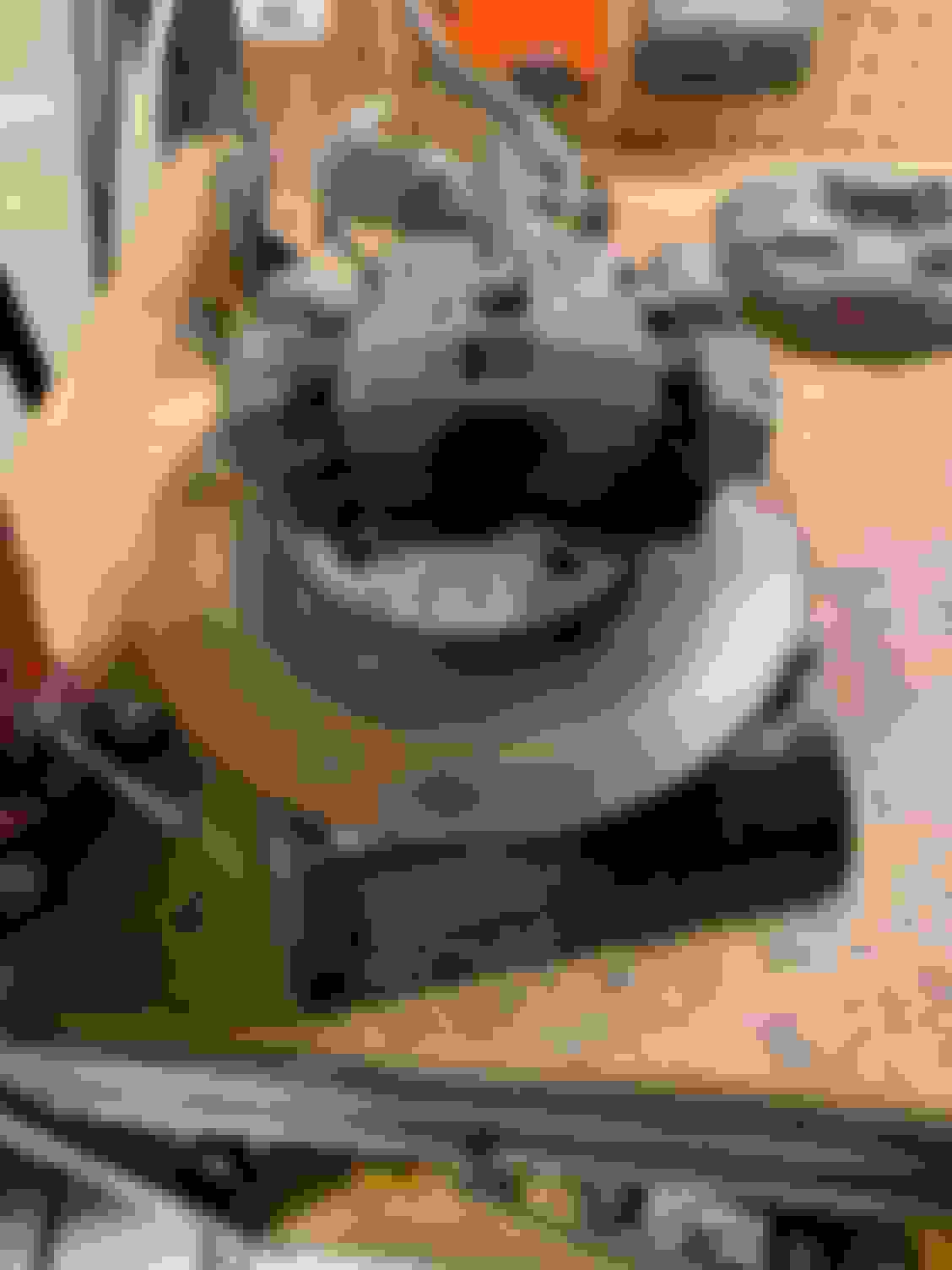
Next step was taking the knuckles apart and rebuilding them. I started by pressing out the hub using a bearing splitter & press.
After that I removed the snap ring that holds the bearing in place and pressed it out. The 38mm socket fit perfectly for this. (Note: I was just using the hub as a "spacer" so I didn't have to reposition everything on the press again)
Last came the rear seal & brake splash guard.
Now came time for re-assembly...
The Getrag Diff setup from V8Roadsters allows you to either use the stock hubs, or upgrade to their forged hubs with ARP studs. After seeing some of the hub failure threads...an easy choice was made. The new hubs in all their shinny glory.
First step was installing the studs into the hubs. I pressed them in using some deep sockets to hold the hub up.
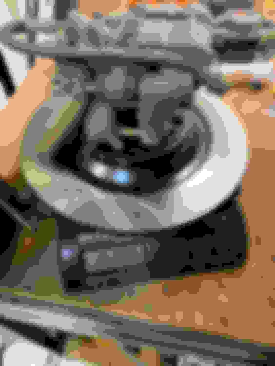
Next up was pressing the bearings into the knuckles. I put the bearings in the freezer over night and lightly greased the knuckles. I was hoping they would go in easier this way, but they definitely still had to be pressed in. I used an old bearing to press them in and marked it so I knew how far they had to go. Looking at this picture, you can see the condensation on the bearing from it being in the freezer.
After the bearing was pressed in, I reinstalled the snap ring & the new seal.
And time to press in the new hub! Note: I looked everywhere to find out how far you are supposed to press in the hub. This ended up being an issue later in life (I'll share with the brake writeup) but the short answer here, you press them as far as they will go.
And Voila! We have the rear knuckles and hubs completed!
I had the choice of going with the Chevy Diff or the Ford Diff with the V8Roadsters kit. I chose the Chevy / Getrag diff, because it's a little lighter and a bit easier to fit the exhaust around. I also went with the 3.42 ratio. Ryan Passey did the actual math and laid out graphs on the diff ratios. I used his info which you can find in his build thread. (Thanks Ryan!)
The diff I purchased was sourced by the yard that sold me the LFX pull out I purchased. I don't know the mileage, but the fluid looked decent when I drained it and the rubber bushing (goes bad quickly) was still good, so fingers crossed it's will be fine.
Axle Seals
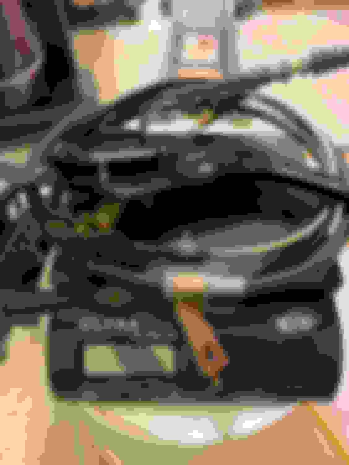
First thing I did was change out the axle seals. Since I've had these go bad on other cars I've owned and these still had the markings of being the original 15 year old ones...I found this while changing them...(the sides were capped properly...but who knows?!?! Maybe its not as decent as I was hoping.)
After fishing out this plug, the new seals were put in and ready for the next mod. (sorry I forgot to take a picture of the new seals in.)
Front Bushing
Next change was the front bushing. These are notoriously weak and have holes in the bushing to give a more cushy ride in the Caddy that this diff came from.
To upgrade this, there are a couple choices out there, that require you to push out the metal sleeve along with bushing & it's not easy. The "easy" option (and cheaper) was to pull out the bushing and leave the sleeve and stick some poly bushings in the sleeve. Smarter people than me have already figured out that Energy Suspension part number 3.2125 works, you just have to cut the bushings down to size.
First step...Pull out the old bushing. I pressed this one out like I did some of the control arm bushings.
There was a little bit of rubber left in afterwards where it attached to the metal. I scrapped it off with a little heat and a small file.
The bushings do need to be cut down a little. Nothing fancy here, I pulled out a coping saw and hand cut it very quickly using the vice to hold it / make a straight cut. You do this to both bushings & you need to cut the metal sleeve to size too.
Slide the two cut bushings in and the sleeve & you are ready to bolt it into the subframe. (Only picture I could find was it already bolted in.)
Vent
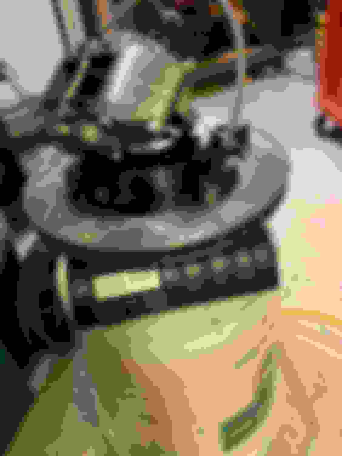
Since my car is for the track, I also need to make a mod to the vent so it doesn't puke fluid on the track. Here's a picture of the vent, it has the white paint on it.
The proper way to do this is to remove the factory vent & tap the hole, thread in a npt hose barb, and attach a hose to it. I was having a very hard time getting the vent out, and basically could only get the top off.
I was a bit worried about drilling & taping the hole, so I decided to try attached a hose to the end that's sticking out of the diff. I'm not sure if this will hold well or not once the car is on the track, but it seems to be holding pretty decent for now, and if it doesn't, I will properly drill and tap this part.
Diff Input Shaft Pin
I'm not sure what the official name of this part on the diff is, but its used to locate the driveshaft true when you install it. The problem is that both the transmission & the diff have this same pin, and it keeps you from being able to install or remove the driveshaft without removing the diff or transmission. Since doing that would get old very quickly, people trim this Pin so that it's shorter and you can then get the driveshaft on and off without any issues. I wasn't sure how much to cut the pin originally, and ended up not cutting off enough originally & had to crawl under the car with a grinder (no fun) and do it again. I ended up with 22mm left from the measurement you see below.
(Note: If you scroll up a little to the bushing part, you will see the pin I'm talking about at it's original length.)
This is the first mention I've seen about that cheap ES bushing solution for the diff. Thanks a bunch for that info as it's going to come in handy for my LFX build too, +1 postcat!!!
The big benefit is not having to remove that metal sleeve. There was a write up on it on a Caddy site if memory serves me/you need more info (I did this a year ago last fall; I'm trying to catch up my build thread). Glad this helped!
With the LFX conversion, you no longer use the PPF that holds the transmission & the diff together. This removes a big chunk of aluminum under the car, but requires a new way to hold up the tranny & diff. For the Diff, we need to weld some tabs onto the rear subframe to hold the diff in place.
I thought the hardest part of this was going to be the placement of those tabs (getting them exactly correct) to tack weld into place, but that really wasn't hard at all. I started with putting the V8R rear diff bar on the diff (this allows you to bolt the rear of the diff up to the subframe as the original torsen bolts into place) and mounting the diff to the subframe. From there I used some scrap pieces of 2X4 and some wooden shims to get everything nice and level, including supporting the front of the diff.
Getting a level on the subframe for side to side level wasn't that big of a deal, but to check front to back on each side there is a metal square & some humps that keep you from getting the level nice and flat on the metal. I found a washer (actually 2 of them together) that was the exact same hight as metal square and used that on one end so I had a "flat" area to put the level. From there you can shim the subframe to get everything level.
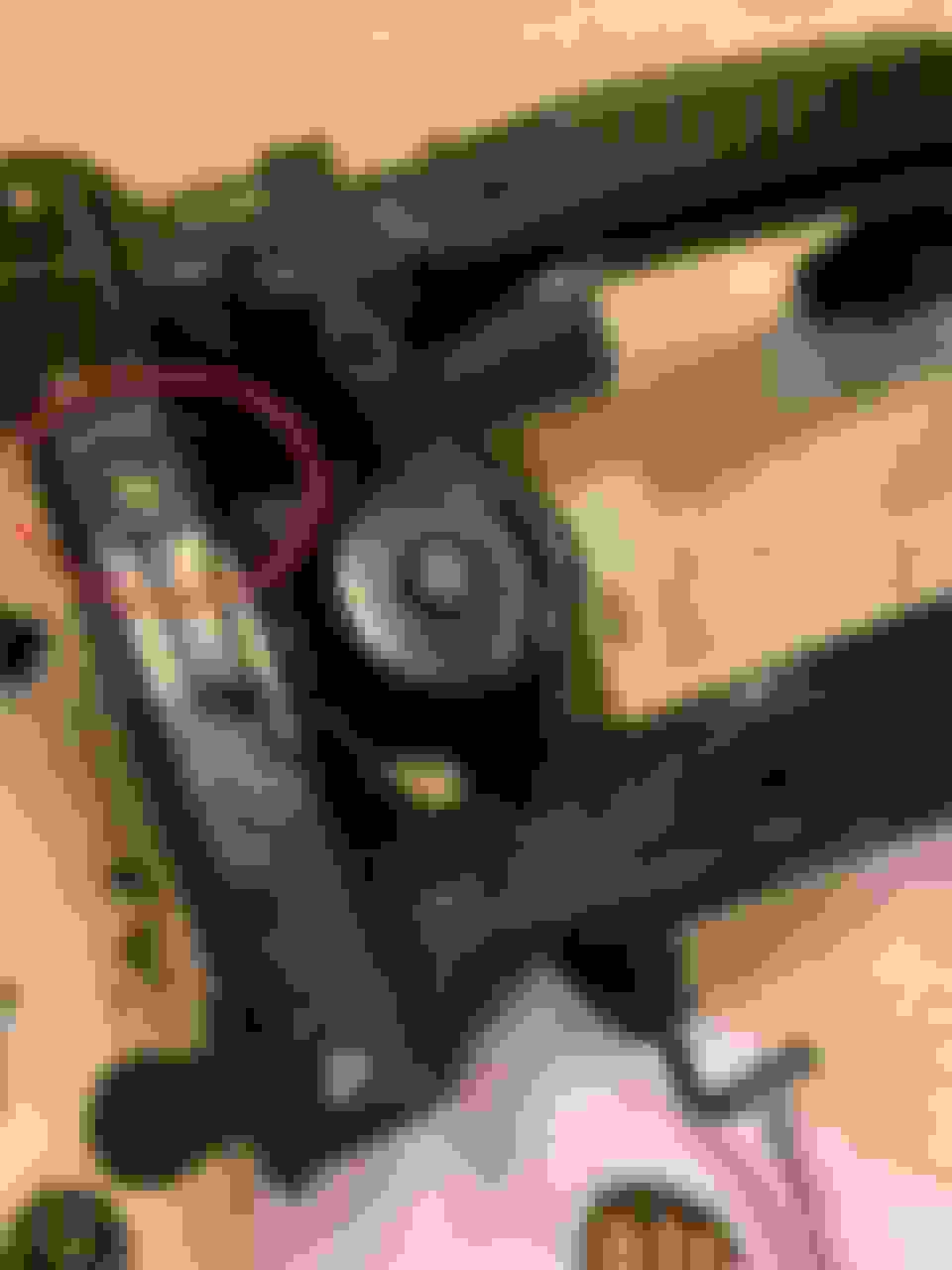
If you look at the level where I have the arrow, you can see the two washers that allow you to use the level on the subframe. (Sorry, crappy picture of this, but best I could find.)
Once the subframe is perfectly level, it's time to level out the front of the diff. The front of the diff needs to be at 1.5 degrees pointed down. I used this cheap *** eye chart of an angle finder to do this, but a digital one (probably one you can use for the camber when doing alignments) would have been easier to work with.
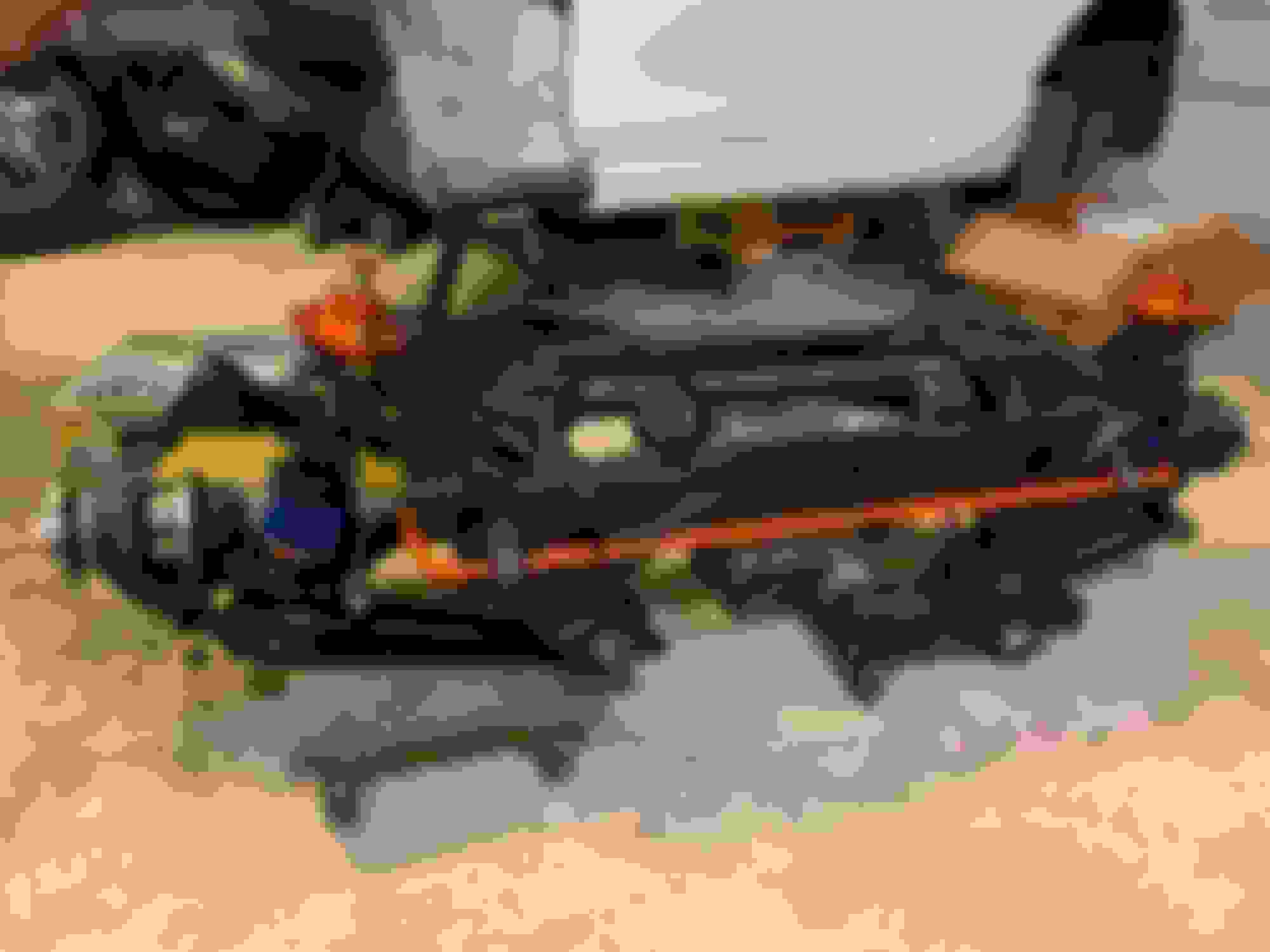
From there I tack welded the front bracket in place and worked on the rear bracket. The rear bracket requires some grinding so it fits properly. The rear bracket is on "top" in this picture, you can see where I did the grinding between the tack weld and the bolt hole.
Here's the bracket with the diff in place, so you can see why it needs to be ground down.
Welding this all up was a bit of a challenge for me because I couldn't get the torch/gun in easily, the lip of the subframe was in the way from approaching it the direction that would have been easy. So if you are new to welding (like I am / especially was when I welded this) this will be a little challenge and don't expect it to be a pretty weld.
Quick spray with some paint to keep from rusting & ready for reassembly!
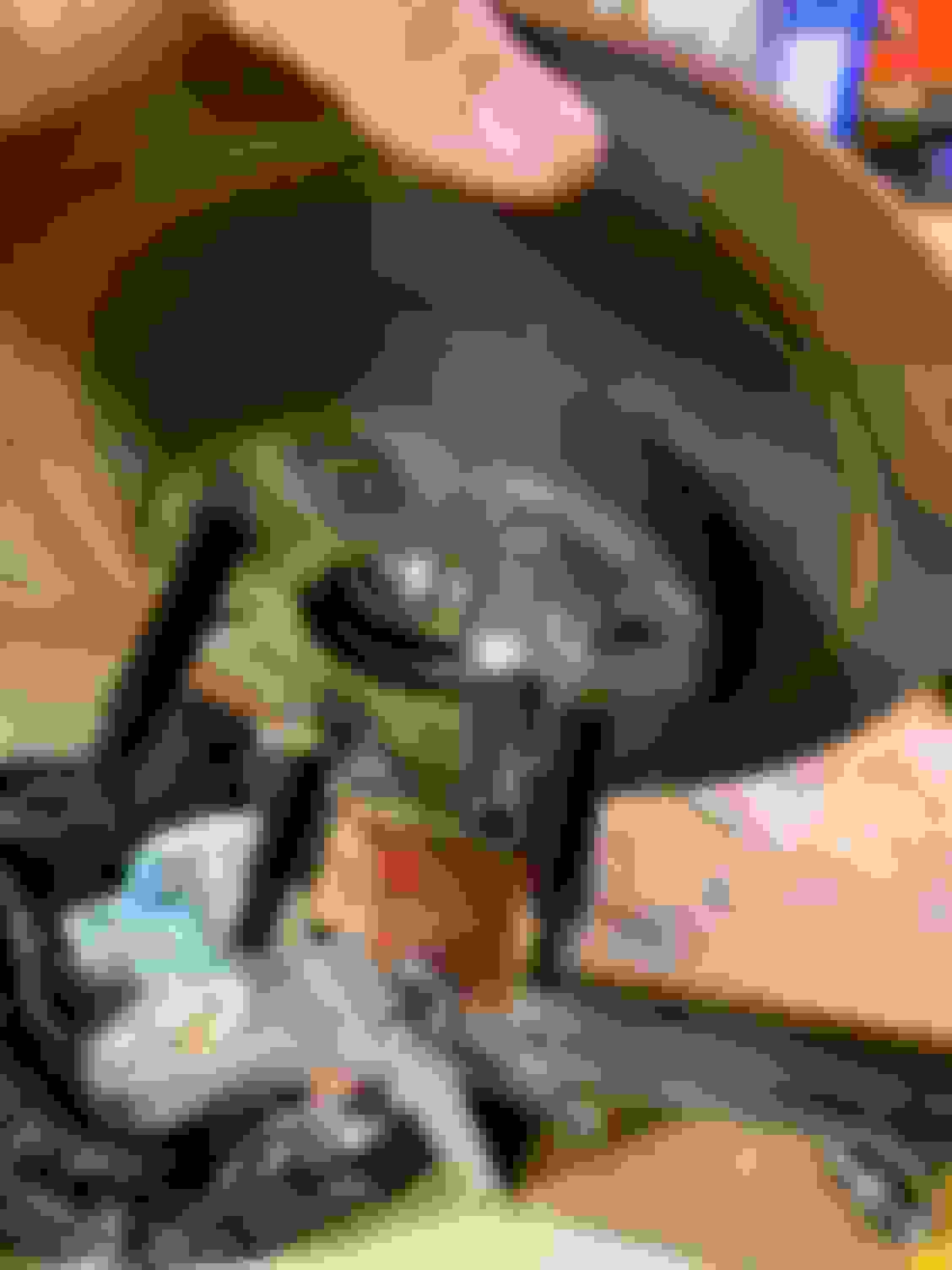
Reassembly made me feel good. I finally felt like I was starting to put the car back together verses pulling it apart & cleaning (which has been the majority of the work so far.) I installed the new V8R half shafts (one is 1/2 longer and they have a specific side, which I don't remember, but mine had little labels attached telling you) Since I never saw the diff with half shafts, I wasn't sure if they were all the way in or not. So I ended up pulling them back out and reinstalling again to make certain. They do have a click when installed, but they also appear to still need to be pushed in if you don't know any better. (I used some white lithium grease on these when installing.) You can see the space here.
With the half shafts in, I installed the control arms with the sad fab bearings, the hubs/knuckles, new Supermiata swaybar, end links, coilovers! I was so excited to see parts going back together!
Hope everyone had a great Thanksgiving! I wanted to get a few posts done last week, but spent most of that time doing handyman stuff & fixing my parents golf cart. I really want to get up to present day with the car...I did most of the work below in Thanksgiving week 2019, so only 1 year behind on the build thread! HA!
Since the rear subframe was done for now, I started to work on getting the front suspension installed on the front subframe. I put the front control arms back on with the new bushings, bearings, & ball joints. I also put the front spindles back on along with new hubs & bearings. Since the Miata hubs are known to be a weak spot with potentially catastrophic results & possible cause for brake pad knock back, I wanted to upgrade these. I looked into blueprinted hubs and Miatahubs. In my opinion, the blueprinted hubs don't really fix a weak point, more just insure you have the best "weak" part available. The Miatahubs are arguably the gold standard, and I'm sure they are super strong. I was having a hard time swallowing the cost. That's about the time I came across a group buy thread on MT for BroFabs Hubs, which use e30 hub/bearings as the base for the kit. The price was reasonable, the hubs are so much thicker / stronger.
You can see the thickness difference between the e30 hub and the stock Miata hub in this picture. (Note: It looks like I'm trying to compare the spacer to the hub, this was the best picture I could find, I took this picture to show the difference in stud length, but you can still see the significant difference in thickness between the two hubs.)
I don't remember why now, but I didn't press these studs into the hub. (or didn't press them fully) I ended up using the double nut method. I also used an old brake rotor to help keeping things straight & actually clamped the brake rotor in the vice to hold everything.
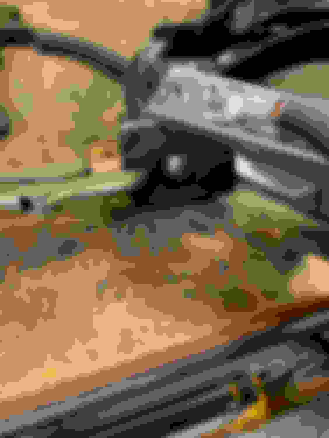
Here's the best picture I could find with the sleeve & other parts. (I'll discuss that brake duct & tie rod soon enough)
And end result...Once everything was installed...
I have one or two more threads on the brakes, and then I stopped working on the car entirely until mid July 2020. So I should be writing about work I did this year soon enough & getting to present day!
LOL...Thank you! That was bugging me and I couldn’t remember why I used the double nut method. You would think having owned BMWs for the last 12 years (and doing the maintenance on them) I would have remembered that they use lug bolts!
With the extra ponies under the hood, I'm going to need more stopping power than the stock Miata brakes can provide. So time for an upgrade. This is one item that I just want to work, and work perfect, so I decided overkill was in order. I ordered up the Stoptech STR42 & STR21 kit with floating rotors & PFC pads. For better brake feel (I hate the long pedal on the stock Miata) I went with a 1" Master Cylinder , proportioning valve & a master cylinder brace. Lastly to keep things cooler, I ordered up 3" Singular brake ducts.
For some reason, I wanted to see how much weight savings there really was. I had a hard time believing I was saving up to 33 lb according to V8R. So out came the scale. I had a set of 1.8 and Sports I could weigh as comparisons. My guess is that "Sports" would weigh the most and be closest to the 33 lb savings. (I don't have 1.6 brakes to check, but I'd have to guess they are the lightest) For each "weigh in" I weighed the rotor, caliper, bracket & bolts, pads, and brake hose...everything that I'm swapping so I had a true apples to apples comparison. For items that were worn, I show both the worn weight & what I added back as a guesstimate for if they were brand new.
Rear Brakes Weight: V8R says it removes up to 7 lb per corner or up to 9 lb per corner if you use their 2 piece rotors in the back. I went with the cheaper 1 piece sport rotor option, so 7 lb is the number to aim for. Let's see how close we can get to that number.
1.8 Brakes weighed in at 13.4 lb per corner. (worn pads & rotor...So add approx. 0.5 lb <--Guessing here...to get the weight if they were entirely "new" and you would be at 13.9 lb)
Sports weighed in at 16 lb per corner. (Used pads, I'd guess add approx. .3 lb for "new" weight and you would be at 16.3 lb)
Parking Brake lever & Cables 3.9 lb total (Each cable weighs .9 lb)
Stoptech STR 21 weighed in at 13.2 lb per corner
So more like 3.1 lb in unsprung weight savings if you were using the Sports, or 4 lb per corner if you want to subtract out the parking brake cable too. (STR 21 doesn't have a parking brake). So 4 lb per corner in weight savings & what should be a better caliper. I also removed the dust shields, and Parking Brake Lever / the center parking brake cable, but didn't count those in the per corner weight savings. I'd guess that's about 2.5 lb of weight savings which I'll include in my overall number.
Front Brakes Weight: V8R says the fronts will save you up to 9.5 lb per corner.
1.8 Brakes weighed in at 17.9 lb per corner. (used pads & rotors, I'd guess add approx. 0.5 lb for a more accurate comparison and you are at 18.4 lb)
Sports weighed in at 23.8 lb per corner. (I had new pads & rotors for this weigh in)
Stoptech STR 42 weighed in at 15.8 lb per corner.
Looks like I'll save 8 lb per corner over the Sports & have bigger / better brakes. Not bad. I also removed the brake shields and added back brake ducts. I'm going to say that's a wash. The new duct hose & clamp will add a little weight, but I don't have that measured and cut to add that to the total. Probably safe to add 1 lb per side there.
I never weighed the Master cylinder, but it is a bit larger than stock so guessing 0.5 lb more. The Master cylinder brace was 0.6 lb. The proportioning valve I'm going to say is a wash since it's replacing the stock valve. So we can add 1.1 pound to the overall brake system weight with these changes.
So what sort of weight savings are we getting overall?
Using "Sport Brakes" (entire brake system) I'm removing about 21.6 lb from the car with 20.2 lb of that as unsprung weight.
Using "1.8 Brakes" (entire brake system) I'm removing about 6 lb from the car with 4.6 lb of that as unsprung weight.
(You can add 3.1 lb of entire brake system weight savings back & 2 lb of unsprung weight savings if you don't include the master cylinder & duct changes)
So a bit less than the V8R guesstimate on savings, but I would have easily chosen to add weight to the car for better brakes; I'm going to count this as a win. Much bigger brakes with better cooling & (hopefully) much better brake feel along with a drop in weight is a win in my book. Especially since you normally never go "bigger" and lose weight.
Nice job on documenting weights. I was going to do similar as I was skeptical on V8R's claims as well. Nice to see it still be a savings regardless of the 1.8 brakes you have though!


 2
2